
Possibly the most useful board i have designed to date!
Replaces a standard 3.5″ , half height SCSI drive with correct connector layout and powered from the drive connector.
Ideal for drive enclosures or fitting inside a computer.
Still does NOT have parity!!
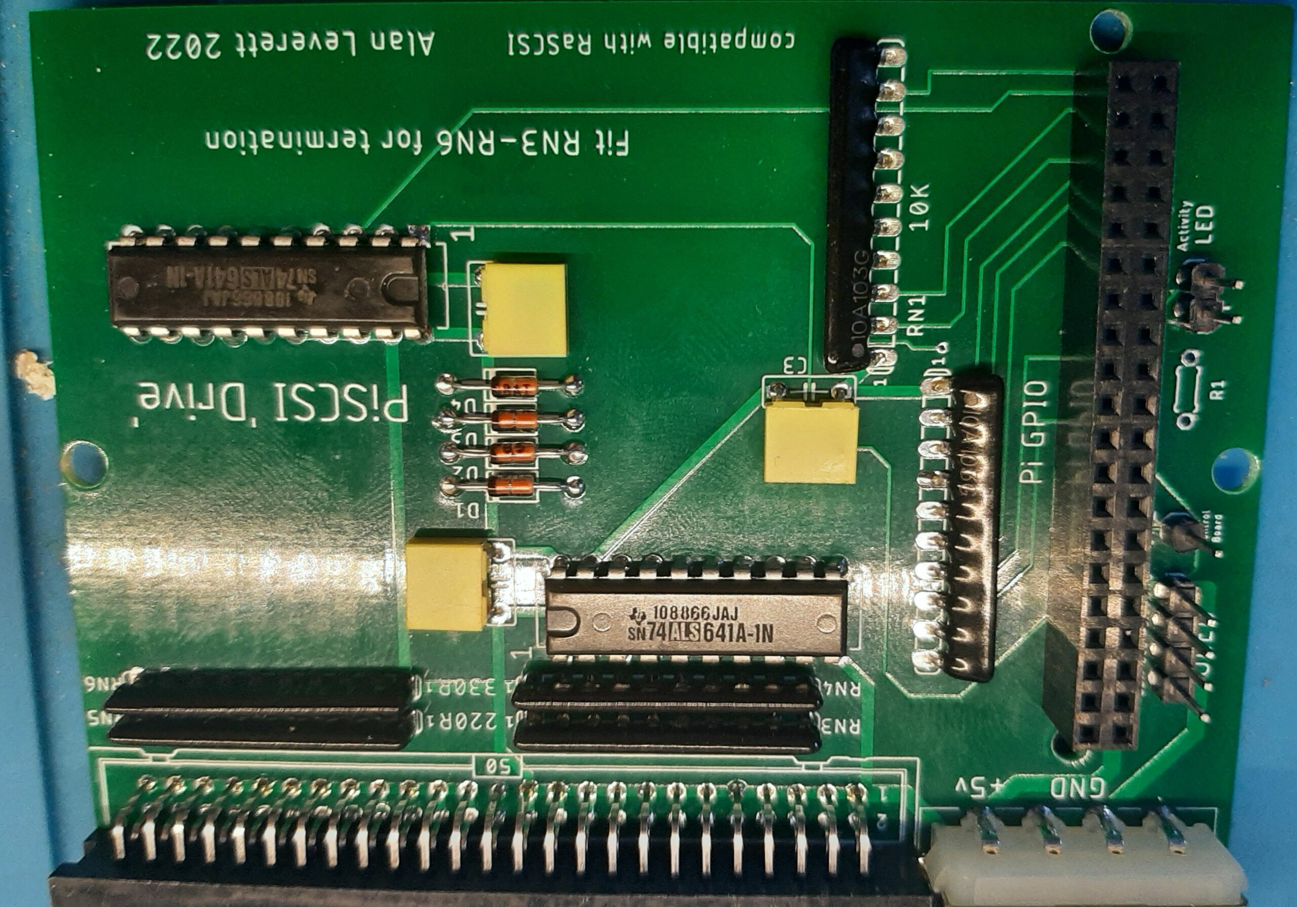
Can be terminated by fitting RN3 to RN6.
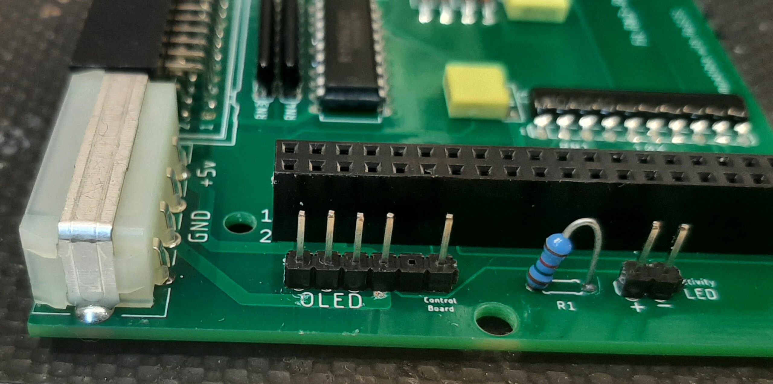
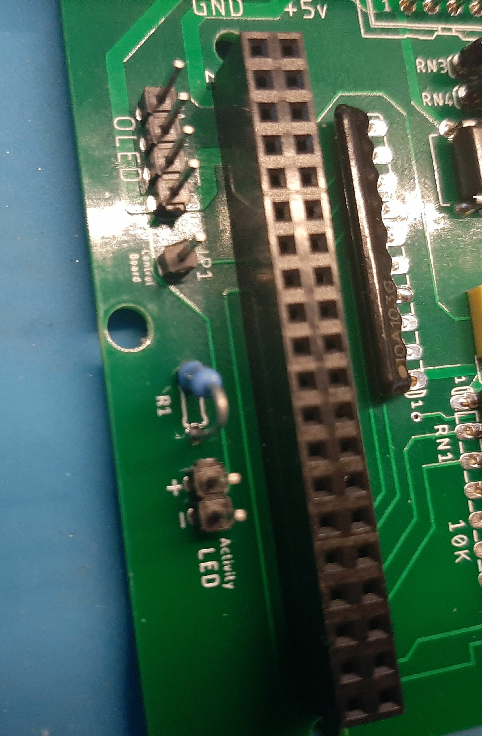
Has connection for the PiSCSI OLED display or Control Board!
Has connection for an activity LED.
Through hole design for easy DIY soldering.
Uses community led PiSCSI software that is constantly being updated and improved!!
( Also compatible with RaSCSI )
You can still access all the USB / HDMI / NETWORK / 3.5mm ports on the Pi !
You can still put moderate heatsinks on the pi !
Here is a parts list:-
1 x TE174804-1 connector
( this is the ONLY connector i have found with the correct orientation. If you fit the wrong orientation one you will put 12v on the 5v AND the pi and blow everything!! )
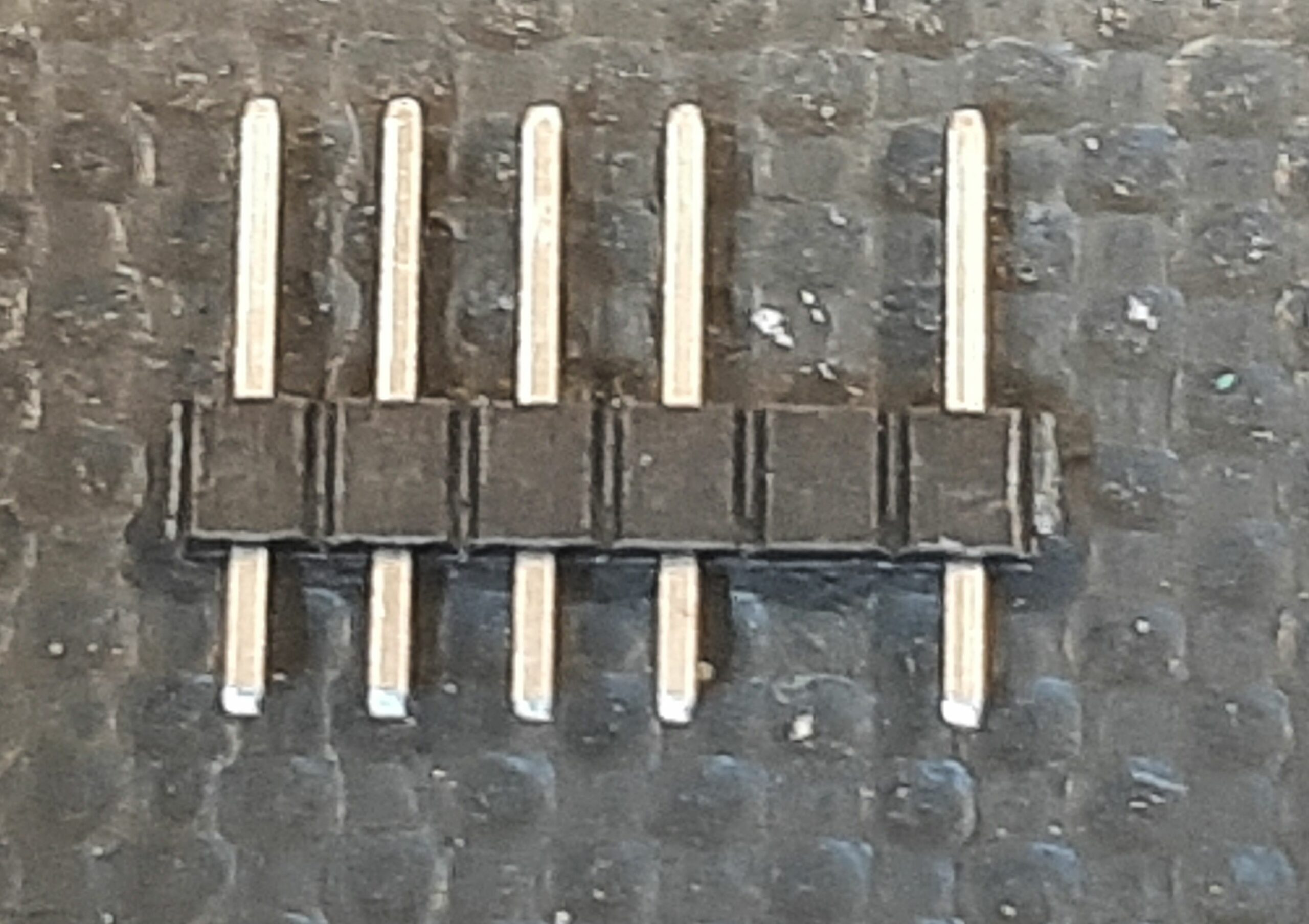
1 right angle 50 pin male box header with 2.54mm spacing.
2 x 10 pin ( 9 resistor ) sil @ 10k.
2 x 10 pin ( 9 resistor ) sil @ 330R ( if termination is required ).
2 x 10 pin ( 9 resistor ) sil @ 220R ( if termination is required ).
3x 0.1uf ( 100nf ) capacitor.
1 x 40 pin idc socket with 2.54mm spacing.
1 x 1k5 resistor .( 1/4 or 1/2 watt will do ).
4 x BAT85 diodes.
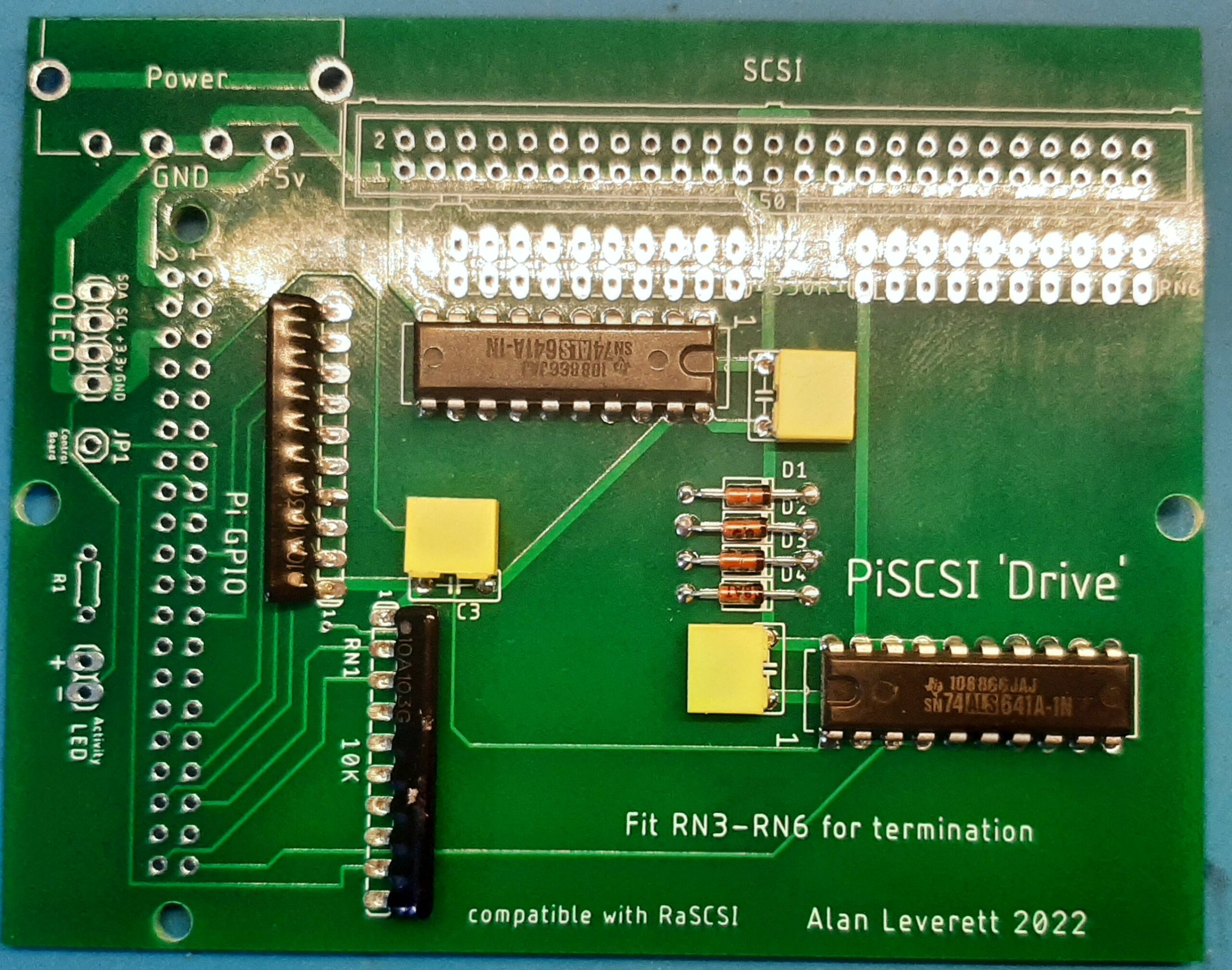
2 x SN74ALS641A-1N.
1 x 4 pin header. ( for OLED or control PCB ).
1 x 2 pin header. ( for activity LED ).
1 x single pin header. ( for control PCB ).
Because of height restraints the chips need to be soldered in so NO IC SOCKETS here!
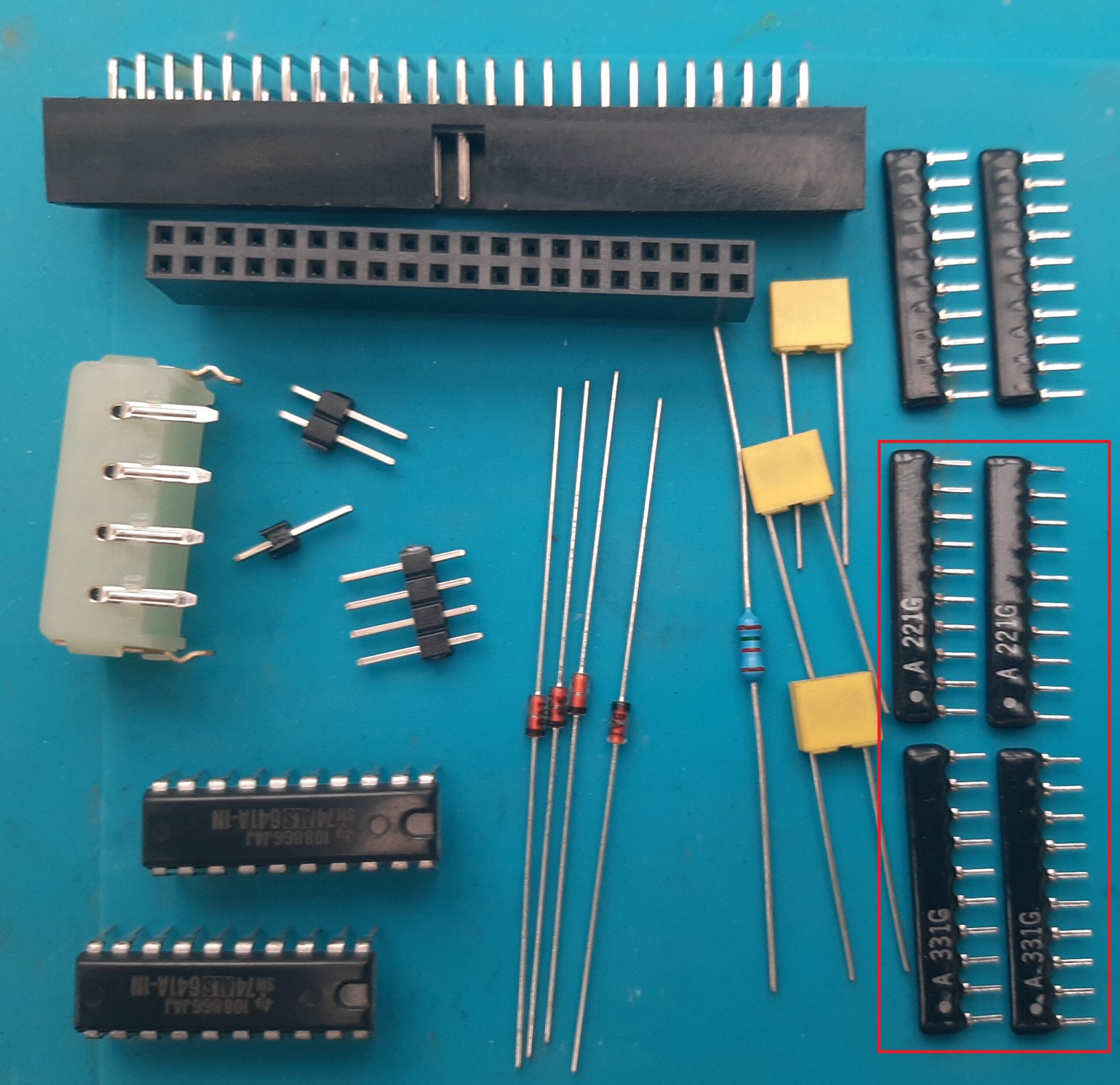
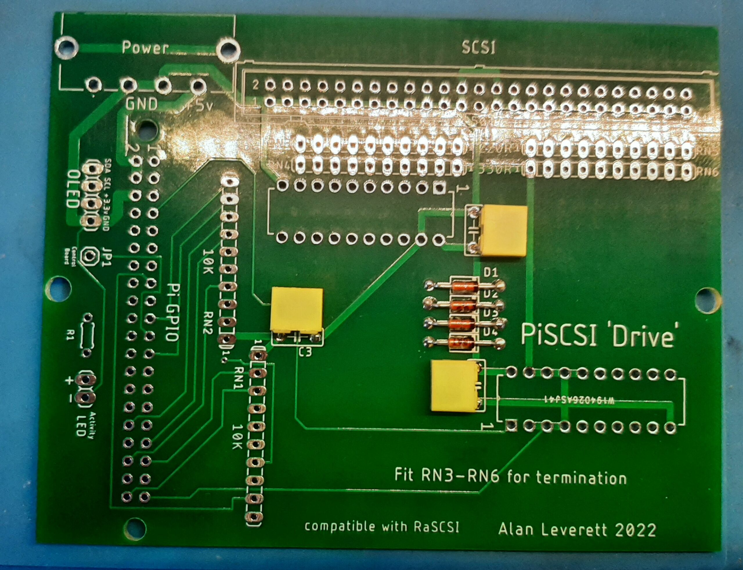
Here is a picture of the parts that you will need .
If you do not need termination then you do not need the parts in the red box.
And , of course you will need the PCB available from PCBWay .
Let’s build it.
I always build by height , so let us start with the diodes.
Then the capacitors , put them in place then bend them to the side so that they lay flat on the board before soldering them in.
Then the 2 10K resistor packs , these need to be bent sidewise as well to allow maximum space above the board.
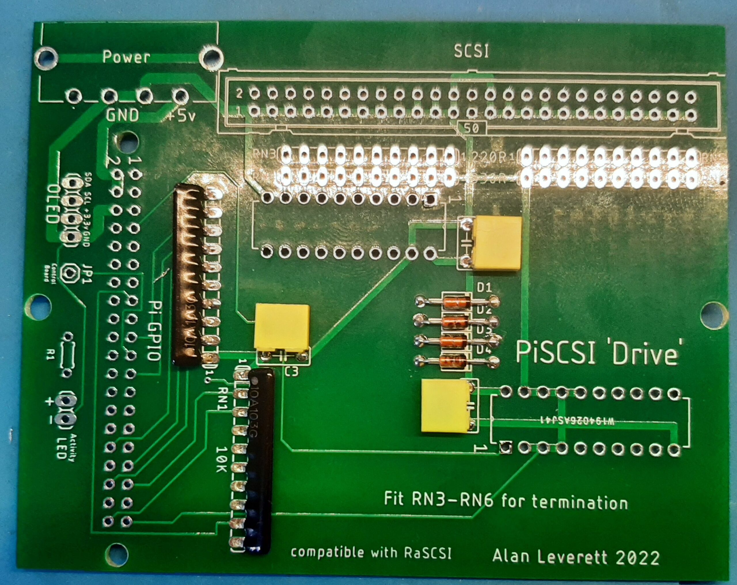
Then the chips .
If you require termination then fit the other resistor packs now ( they can be done at a later date , if you wish ).
Skip this step if you do not require termination.

Now the SCSI and power connector.
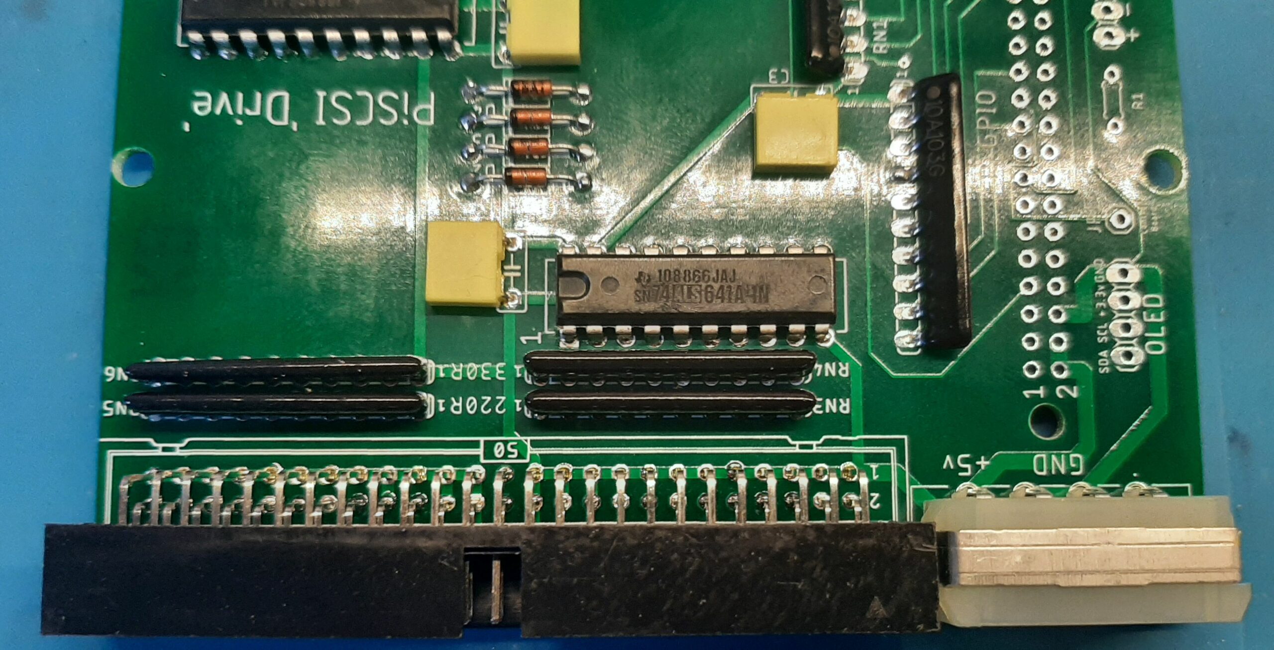
Then the Pi GPIO connector and the pins beside it.
If you are having trouble with the odd pin you can always cut a 6 pin strip and remove the second pin and fit that instead.
Finally the single 1K5 resistor.
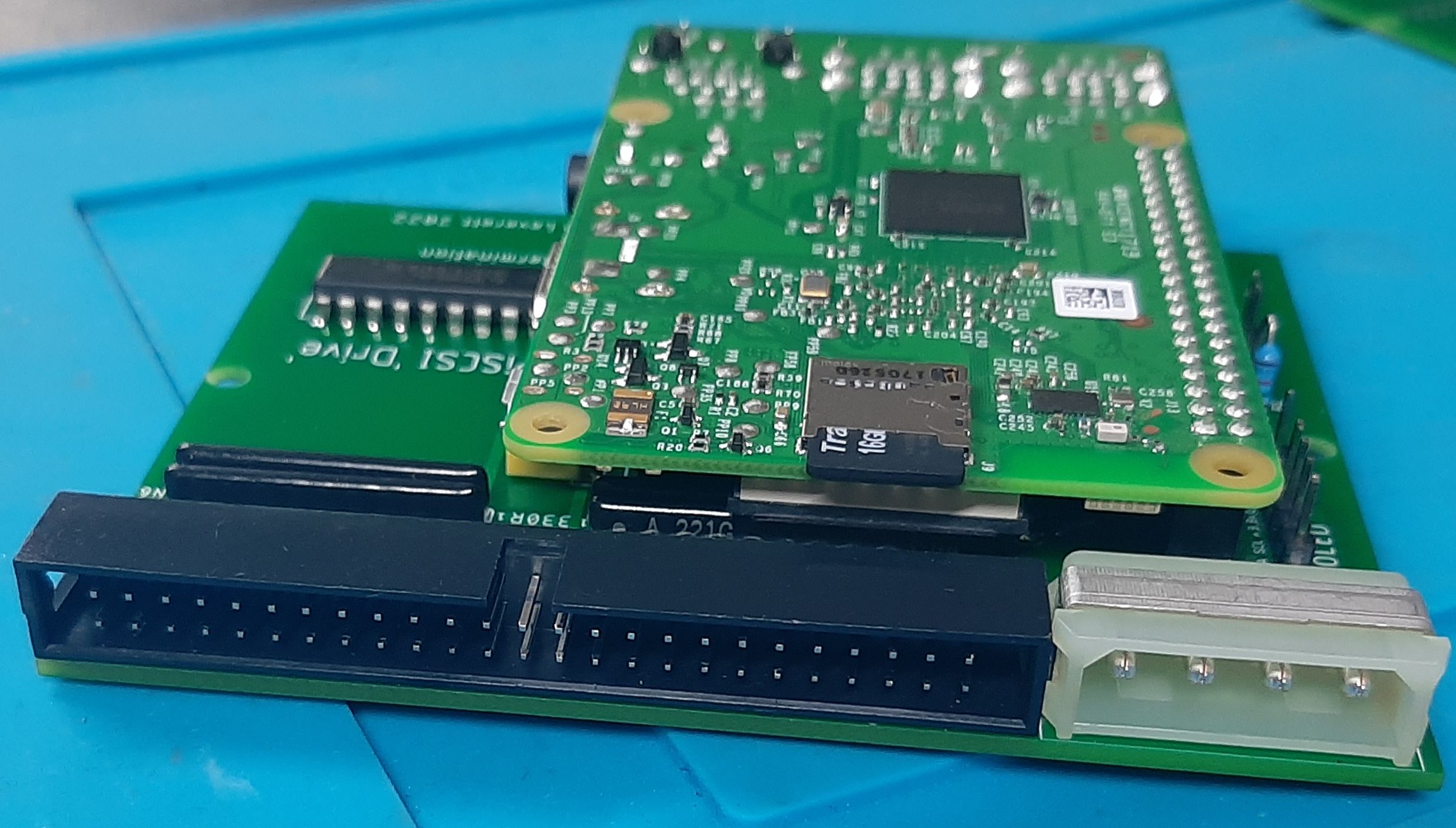
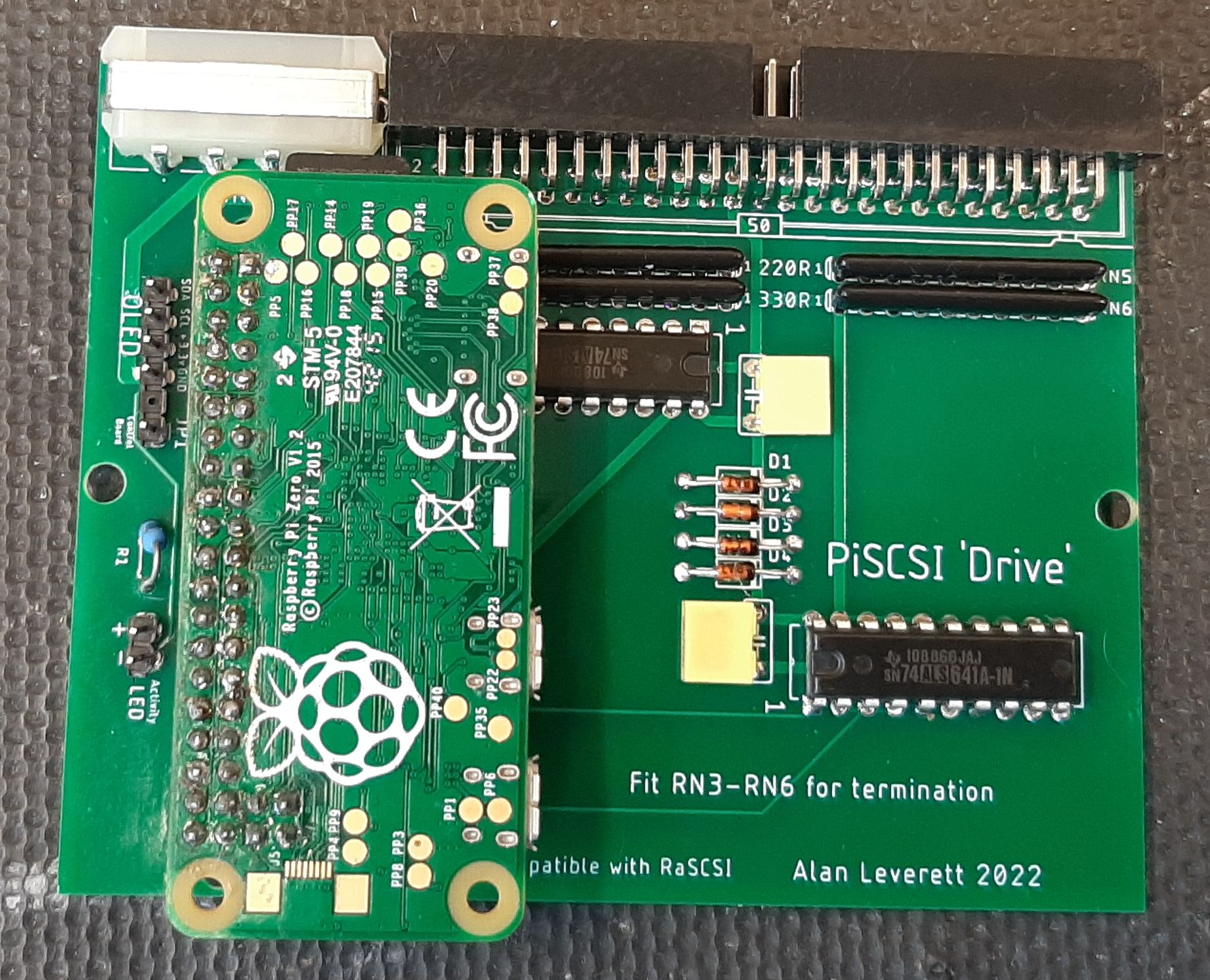
We are now ready to fit the Raspberry Pi . It fits upside down on the Pi GPIO connector A pi2 , pi3 or pi4 , as in the first picture on this post or a Pi Zero or Zero 2 with or without Wifi .
I would use a Wifi version where possible to allow access to the Web interface on the Pi for easy shutdown and set up of drives .
For PiSCSI software setup details please goto the PiSCSI GIT HUB.
You can also chat and get help and support on the PiSCSI Discord.
Expansion options.
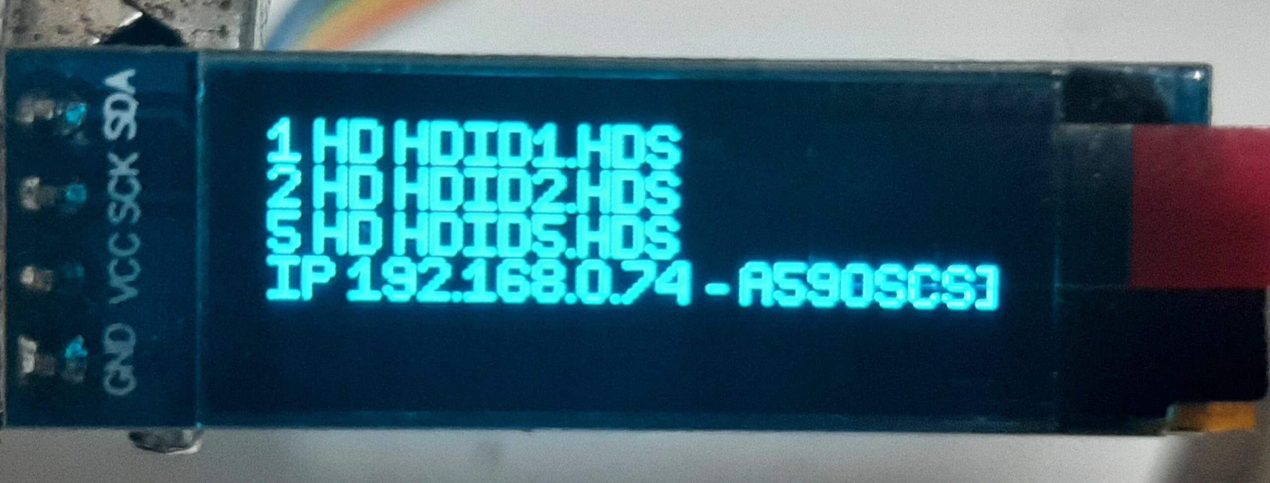
You can fit an oled display that shows the current mounted drives and the IP of the unit.
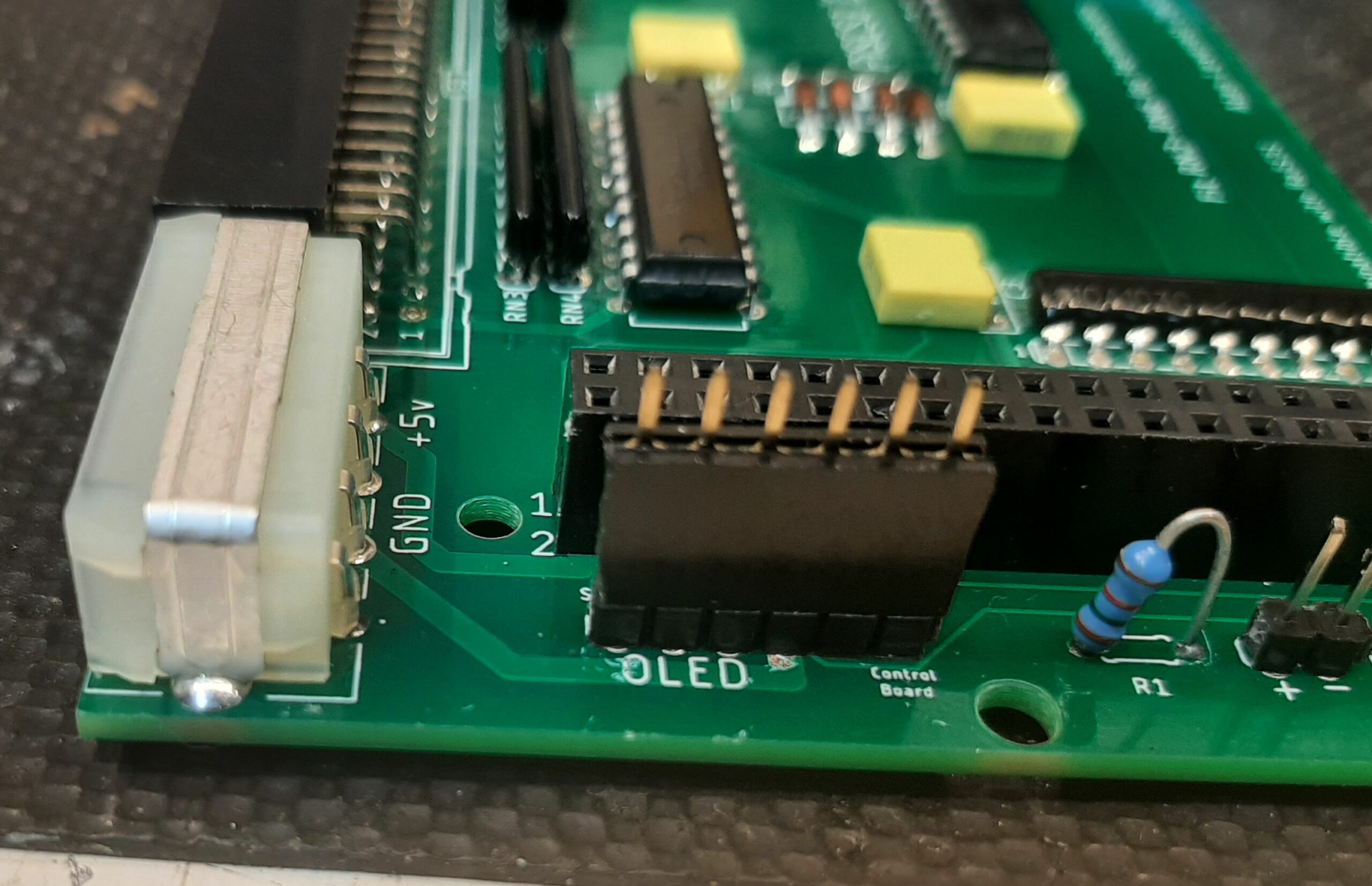
This requires 4 wires to attach it to the PiSCSI ‘Drive’ board via the OLED connector .
Details available here.
https://github.com/PiSCSI/piscsi/wiki/OLED-Status-Display
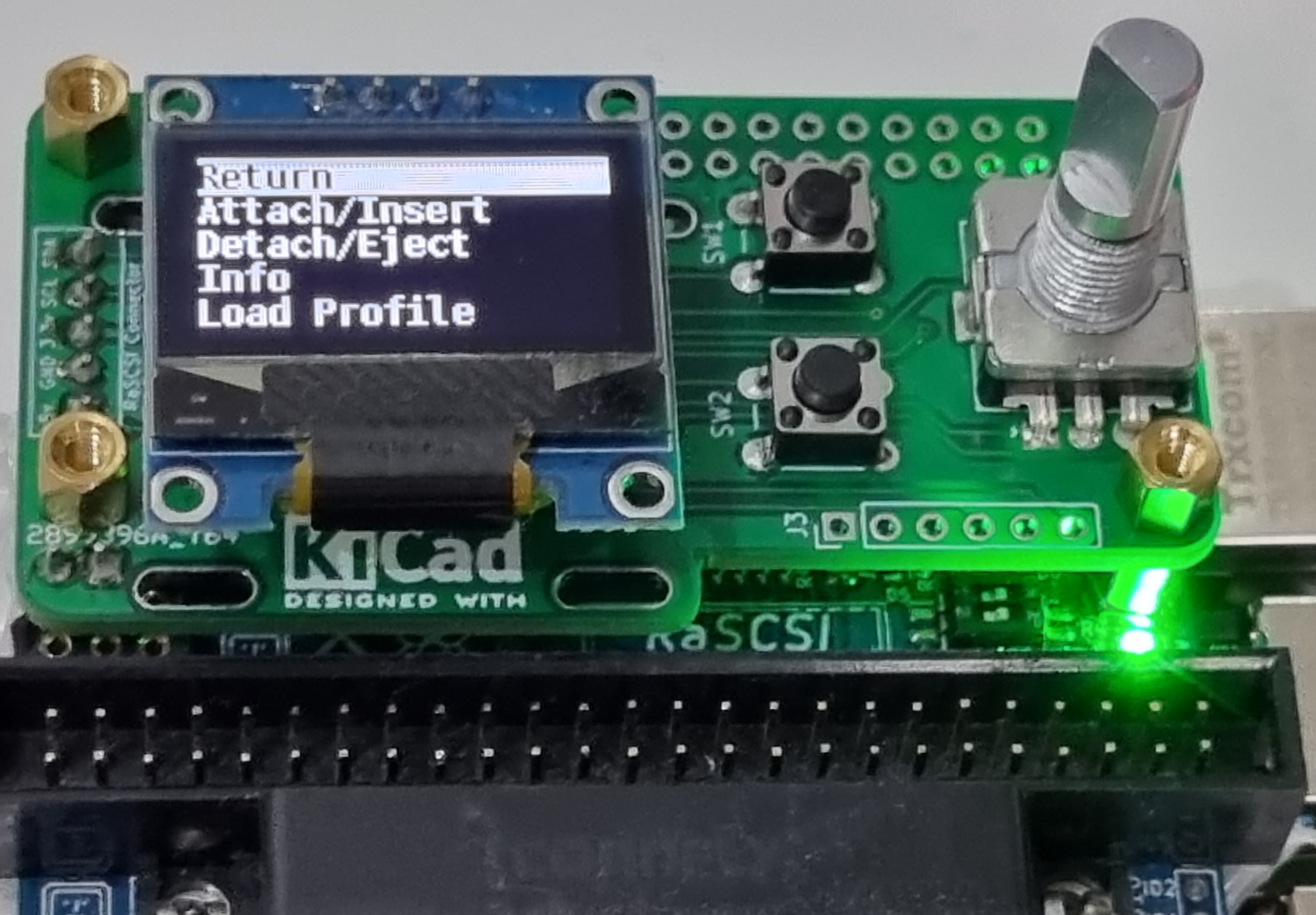
Or you could mount the Control Board to the front of your external drive unit or your drive bay blank.
It only needs 5 wires to attach it to the PiSCSI ‘Drive’ board via the OLED connector and the odd Control Board pin JP1 (GPIO9) .
Details available here .
https://github.com/PiSCSI/piscsi/wiki/PiSCSI-Control-Board
You could use a 6pin connector for the five wires.
Have fun with those emulated drives !
A quick note on termination.
I Know that , at least on the AMIGA , the sidecar drive units and hardcards ( eg. A2091 , A590 ) the on-board drive has no termination set.
This is because the cable from the controller to the drive is so short that termination is not needed as these controllers terminate their end of the SCSI bus and there is very little loss through a short cable.
The only termination required for these controllers is at the end of the external SCSI bus or the end of the internal SCSI bus if you are using an extended cable to connect extra drives.
Only two terminations are allowed in a SCSI chain , if your controller is terminated then you only need termination at the other physical end of the SCSI chain.
Hi Alan,
I note the comment about “No parity” but wondering what the implications of this actually are? I was thinking if this would effect longer SCSI cables.
I have only recently learnt of the Piscsi project and your noticed PiSCSI Drive Board version this morning.
I was trying to work out the differences between your PiSCSI Drive Board and other versions of the PiSCSI; I realise your project is replace an internal drive rather than for use on a DB25 connection. I was trying to work out if the lack of parity was just something which effected your version or the PiSCSI generally.
Any chance if you can help explain this, please?
Thanks
Michael
When things talk on the SCSI bus they use 8 data bits and one parity bit (D0 to D7 and DP) . The parity bit is just a way to check the validity of the data being sent . If the data is odd then the parity bit is a 1 , and if the data is even the parity bit is a 0 . This is just a simple check to verify the data is correct . Similar to the way that parity is used in some computer memory .
I know that the AMIGA and the Apple computers ignore the parity bit . So NOT having parity is not a problem for them , and on other computers it can be disabled so a parity check is not done .
I do know that the PiSCSI (formerly RaSCSI ) project does calculate parity , however I do not think that it actually uses it .
You could also check out the RaSCSI board that uses a similar electronic design , it is fully compatible with PiSCSI as well .