Update : Now includes cad designed pcb
The object of this project is to give the +5v and +9v supply to power ZX81 peripherals without a ZX81.
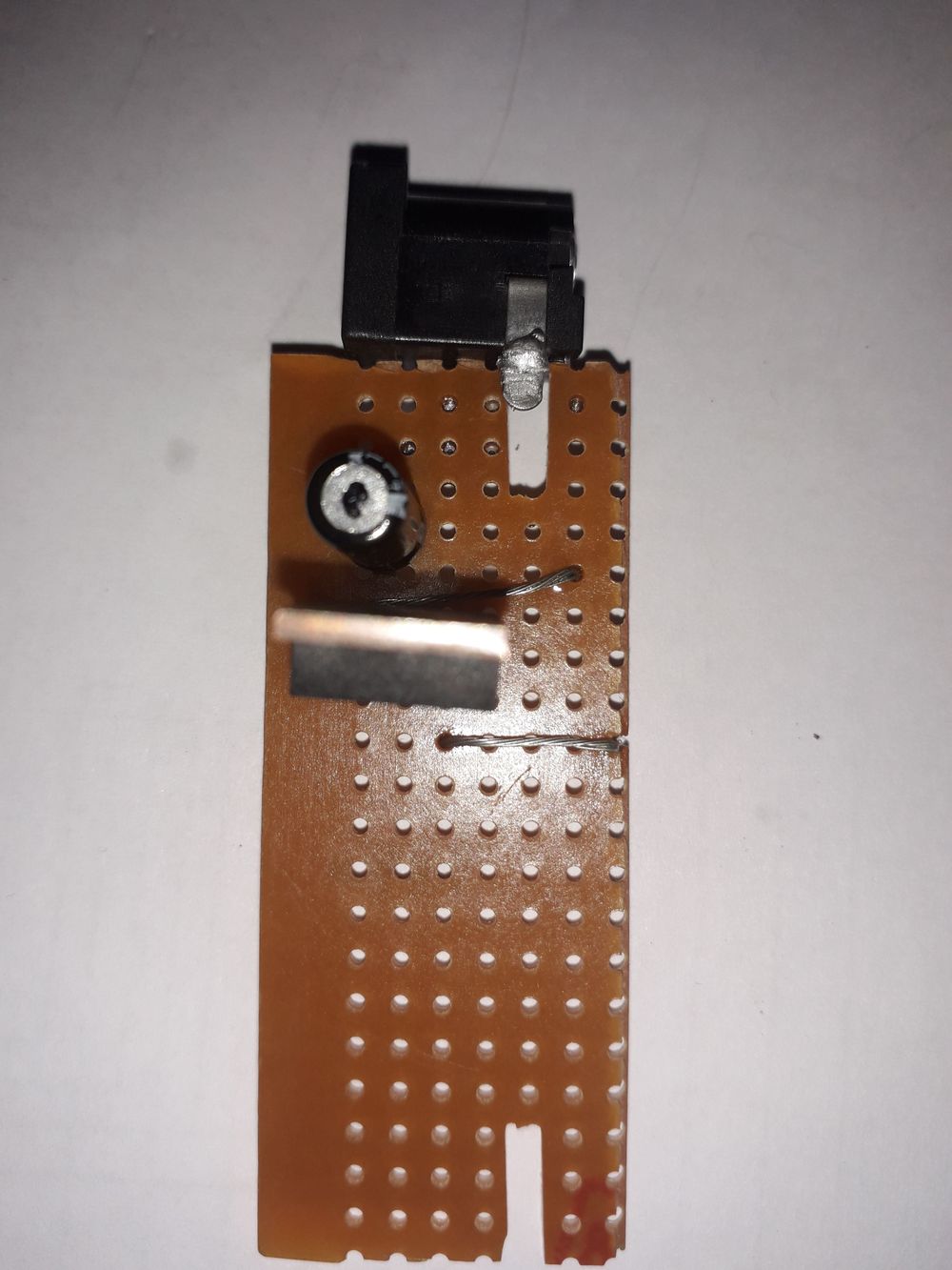
For this project you will need :-
Some Veroboard
10uf 16v capacitor
7805 5v regulator
9v dc supply and connector for it ( mine is center positive )
some hook up wire
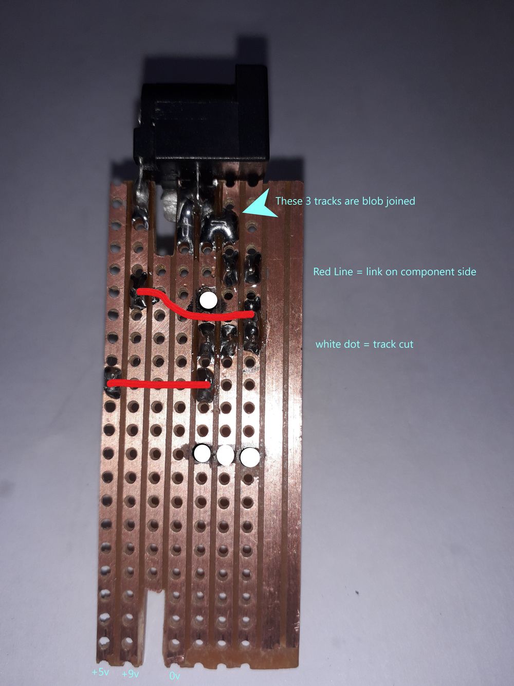
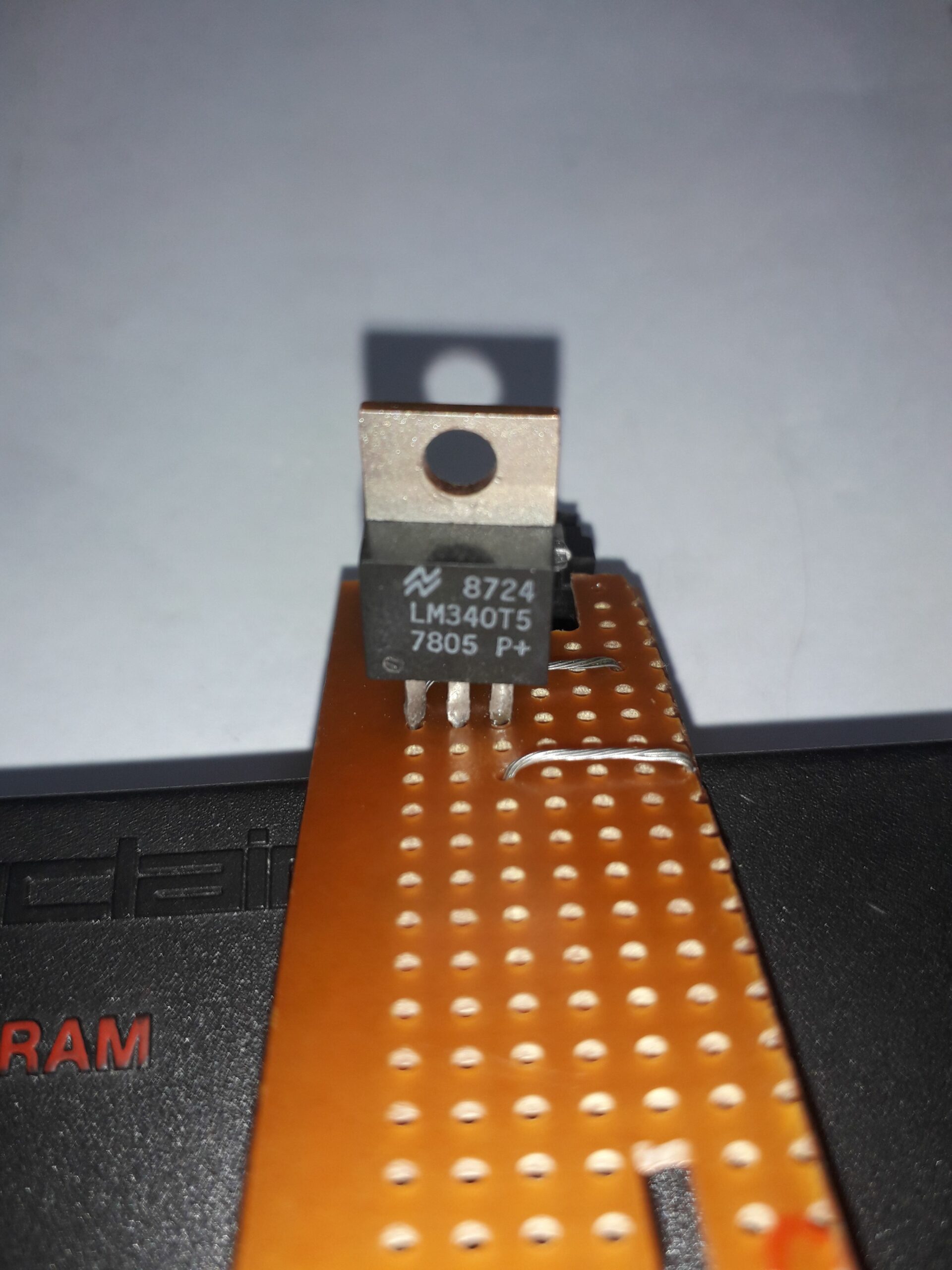
Here it is in use powering a ram pack for voltage testing!
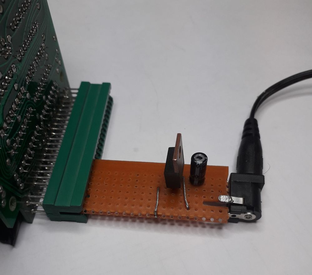
It could be made a bit smaller and tidied up a bit. all 46 pins could be “broken out” to a header if a double sided version was drawn up in a cad package like EAGLE.
I might do this at a later stage! so come back and see if it is done!
I have only gone and done it!!!
PCBWay can supply the pcb now!
Here is an image of the pcb design.
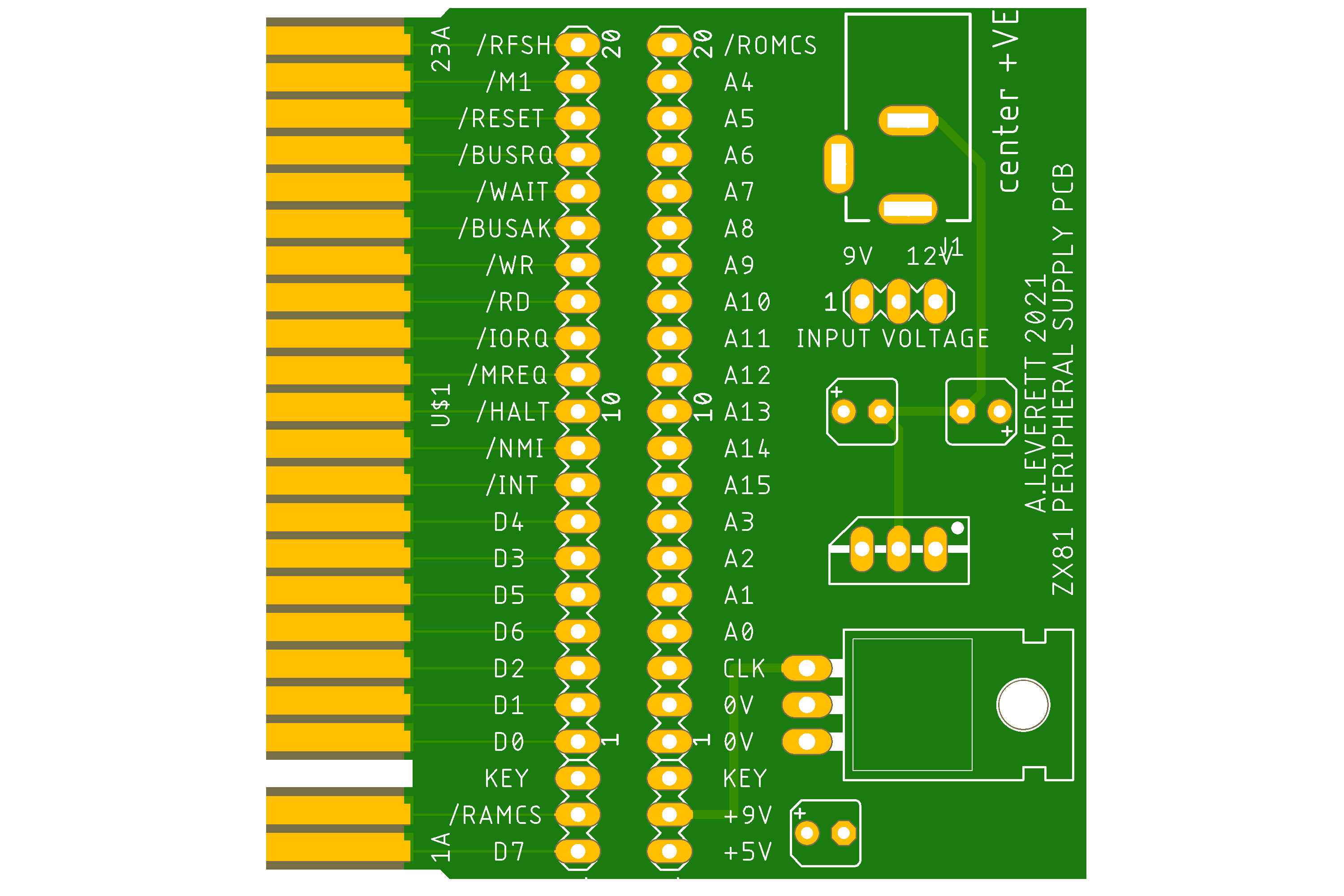
As i could not find a library file of the edge connector for Eagle , I have had to create my own.
Here it is if you would like to use it zx81_edge.lbr .
( Right click and save link as )
It requires two regulators ( 7805 and 7809 ) if you use a 12v input or only a 5v if you use 9v input.
( you can leave out the 100uf capacitor as well for 9v input only ).
My preference is to use 12v so that both supplies are regulated.
The upright one is the 7809 and the one laying down is the 7805. Three capacitors are needed 2 10uf 25v and one 100uf 35v
the one on the right is the 100uf and the other two are the 10uf please note the polarity marked on the board.
Two rows of header pins 23 long ( or two 20 + two 2 ).
Sorry i have not marked the component values on the board as i wanted to minimise clutter and keep the signals clear to read.
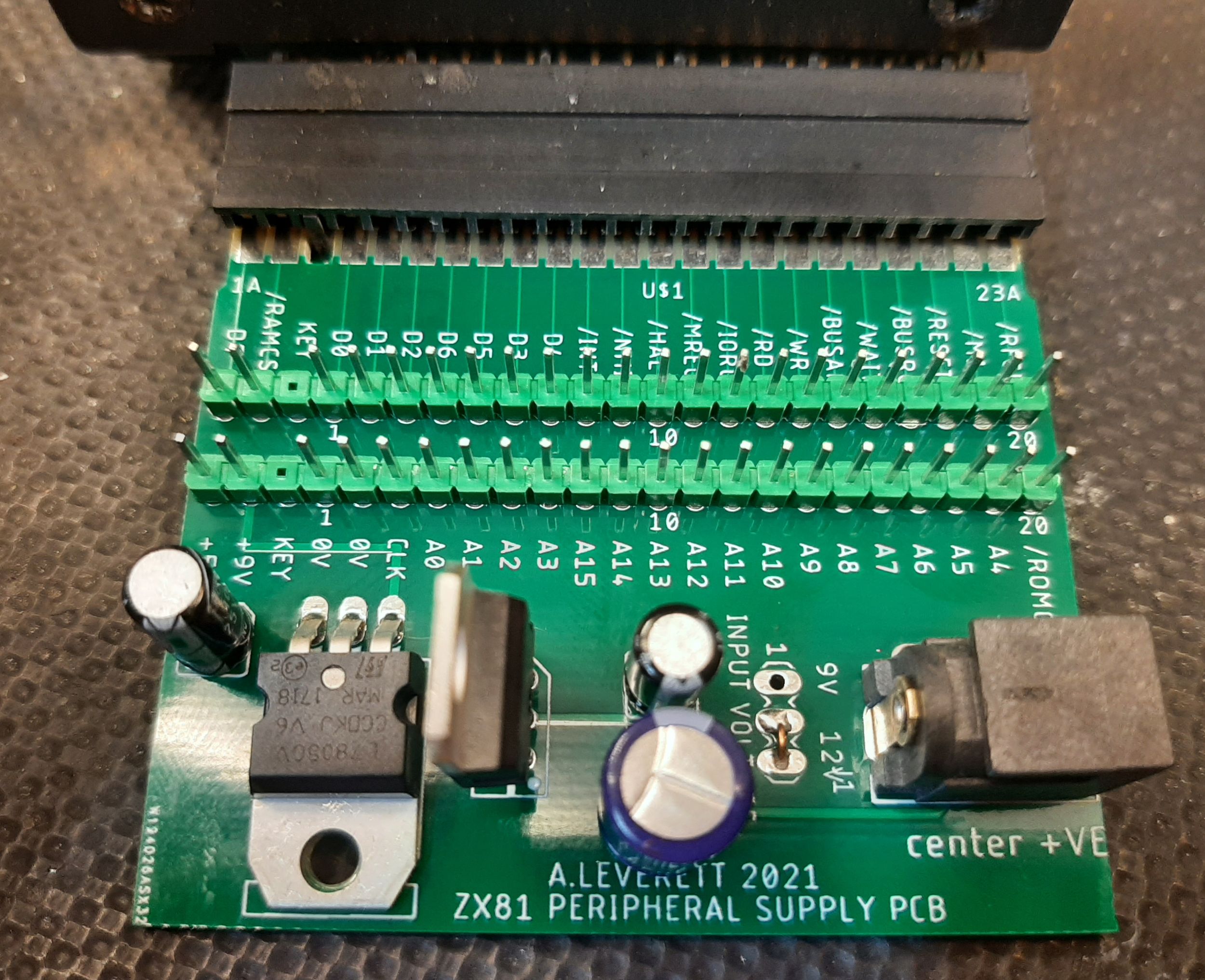
As you can see it lines up perfectly!
Very impressed with PCBWay for doing such a good job with
all of my boards.
This one is set-up for 12v input ( actually it connects directly to the
7809 so the input could be as high as 30v as long as the capacitors are rated for it).
Have fun repairing those rampacks!!!
Next Job :- connect to arduino mega to test rampacks!
I have an Issue 2 pack - so if it works I'll send the details and you will have a…