
The amiga 1200 uses 2 128kx16bit Mask ROMs for it’s kickstart ( the hardware initialisation routines and drivers ) and there is lot’s of information about burning new kickstarts with the 27C400 UV EPROM . This chip is twice the size needed for this , so we should be able to make a dual kickstart switcher with it.
I cannot guarantee that all information here is correct , but will ask people on AmiBay to comment so that it can be verified.
I think the original amiga rom is something like the HITACHI HN62422P.
Here is the pinout for the 27C400.
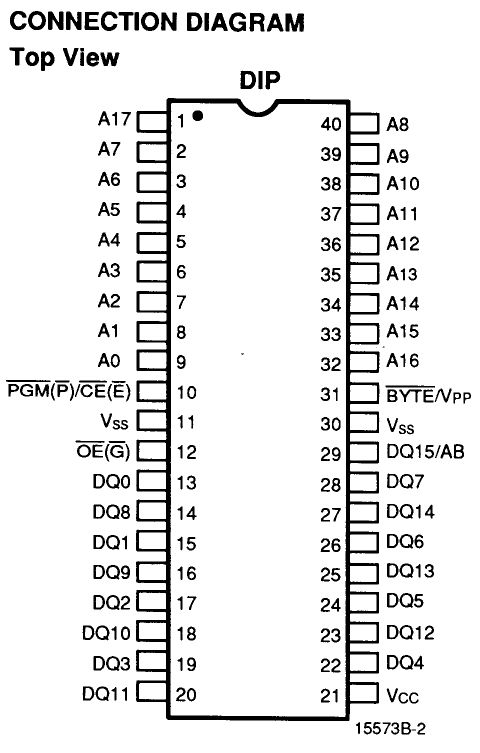
Here are just the differences between the HN62422P and the 27C400
Pin 27C400 HN62422P
1 A17 NC
31 /BYTE BHE
On pin 31 it just has a different label for the same operation and there is no connection to A17 because the memory is only half the size.
Therefore if the chip is selected and read , it does not matter what A17 is doing because the chip is only addressed by A0 to A16 and it will only read from this 128k of 16bit memory. This means that we can use A17 to switch between the upper and lower half of the Rom’s data.
Now to build the rom with switcher.
You will need 2 x 40 pin socket , 1 x 10k resistor ( 1/4w , 1/8w , or SMD it is up to you. ) , 1 x 1pin header , 1 x 3pin header and some hook-up wire.
2 x 27C400 EPROM.
To install into the amiga you will need
one short piece of wire with a dupont connector on either end and a header link , or switch with 2 wires with a double dupont connector on the end .
Don’t worry they just fit to the pins on the EPROM’s.
The first step is to remove pin 1 from both sockets this is so that pin 1 never connects to the AMIGA rom socket .
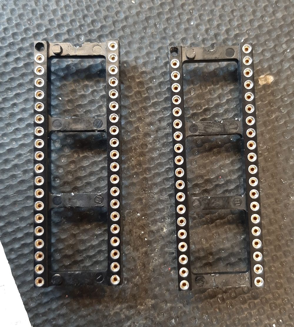
I used my soldering iron to heat the pin from the bottom and push it through.
you can program the chips before or after it is up to you , but it might be easier to program them before.
Then we will glue the header pins to the eprom’s.
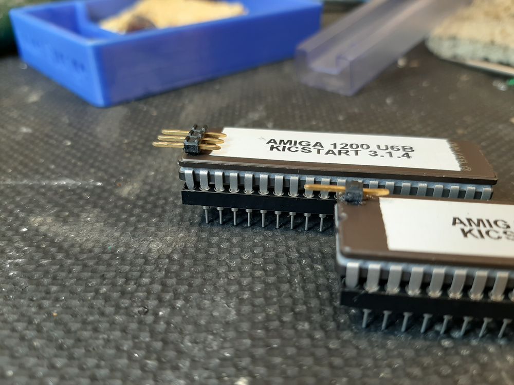
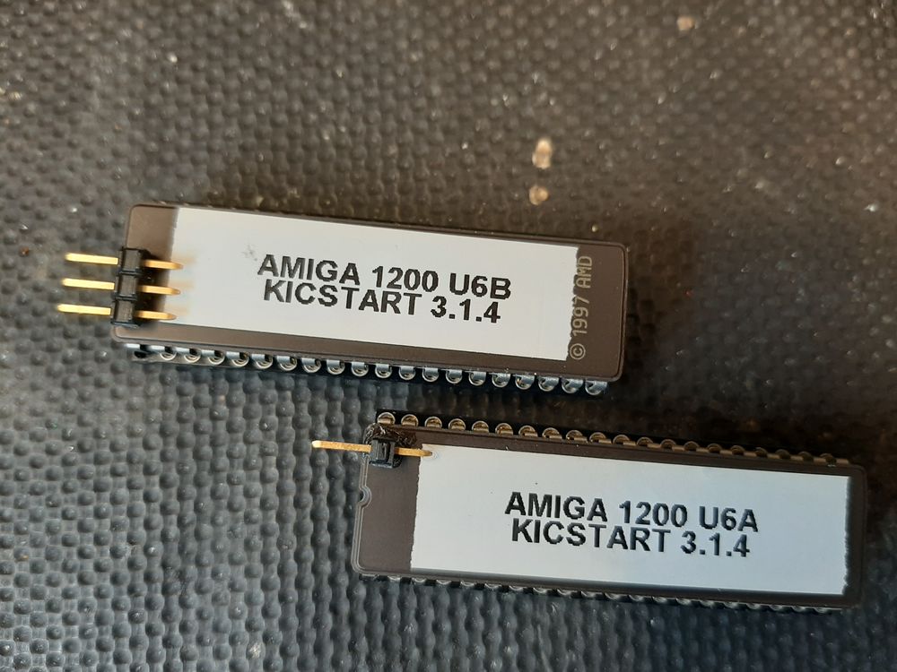
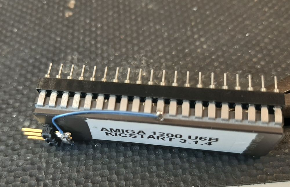
one pin on U6A ( the hi eprom ) and 3 to U6B ( the lo eprom ).
Next the wiring.
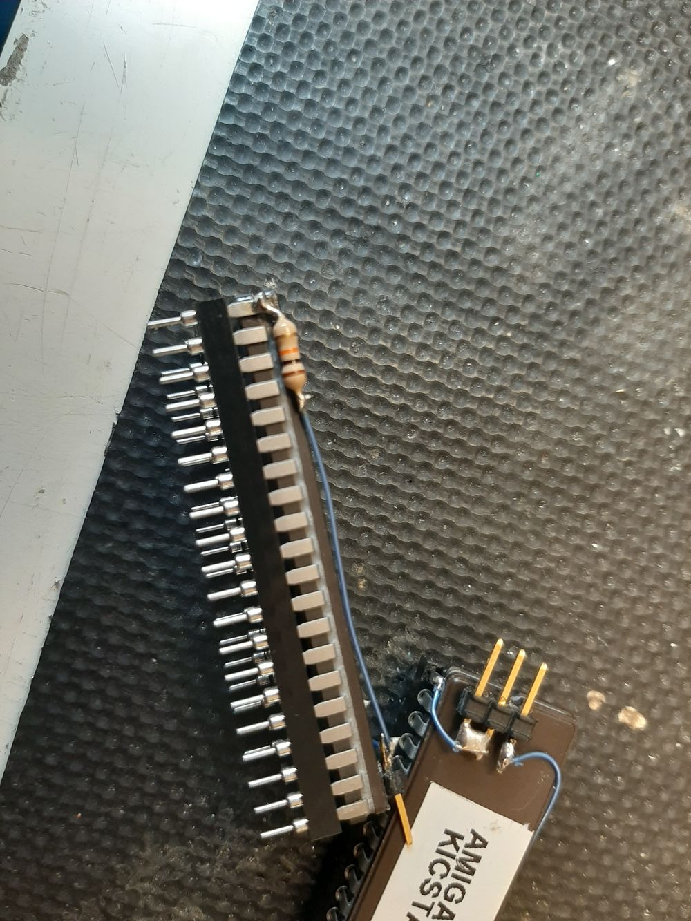
pin 21 of U6A is the +5v supply we need to solder the 10k resistor to it and then run a wire to the pin we glued on top and to pin 1 of the chip.
If we can keep the wires out of the way of the window on the chip we can still erase and re-program it.
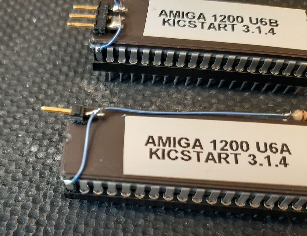
On U6B we will need to wire the first 2 pins to pin 1 and a ground wire from pin 30 of the U6B to the third pin.
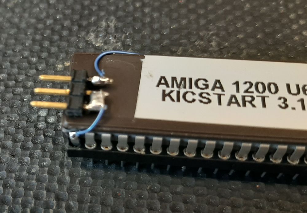
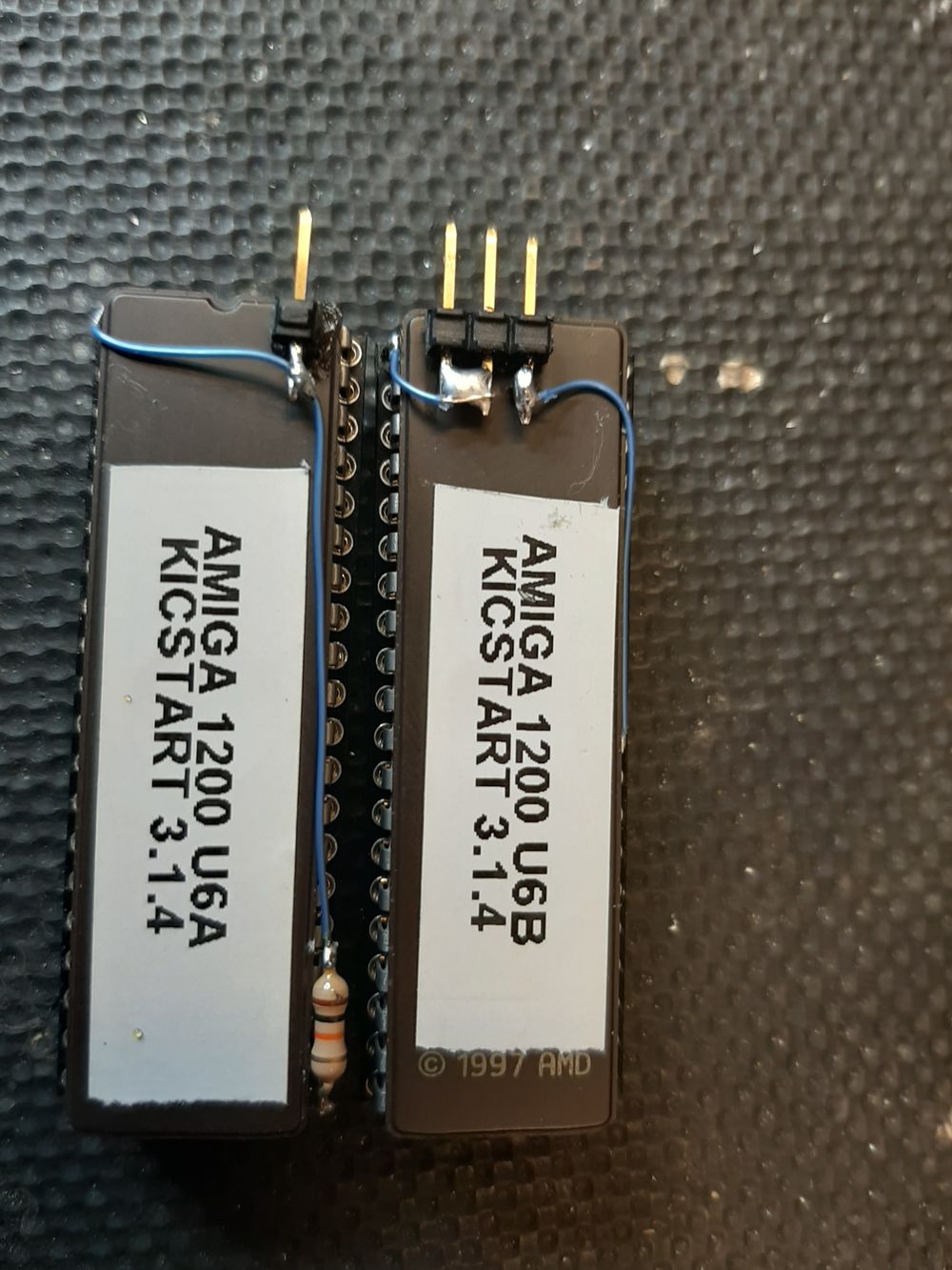
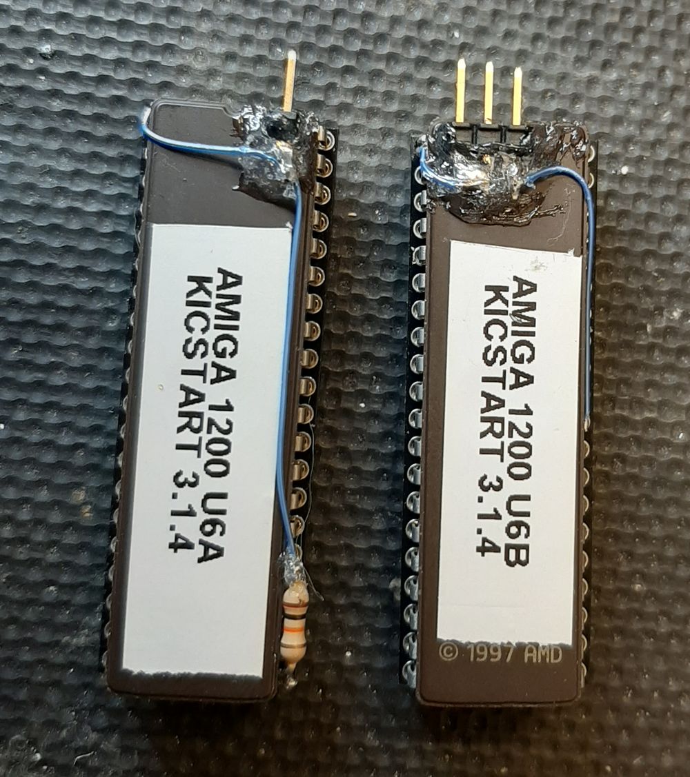
And a final tidy up with some glue or mastic on the solder side of the header pins and the joint between the resistor and wire , this is just to stop accidental shorts to anything.
If you have waited until this point to program the chips you will need to carefully remove them from the sockets .
Then it is just the wiring , you will need one short piece of wire with a dupont connector on either end and a header link , or switch with 2 wires with a double dupont connector on the end .
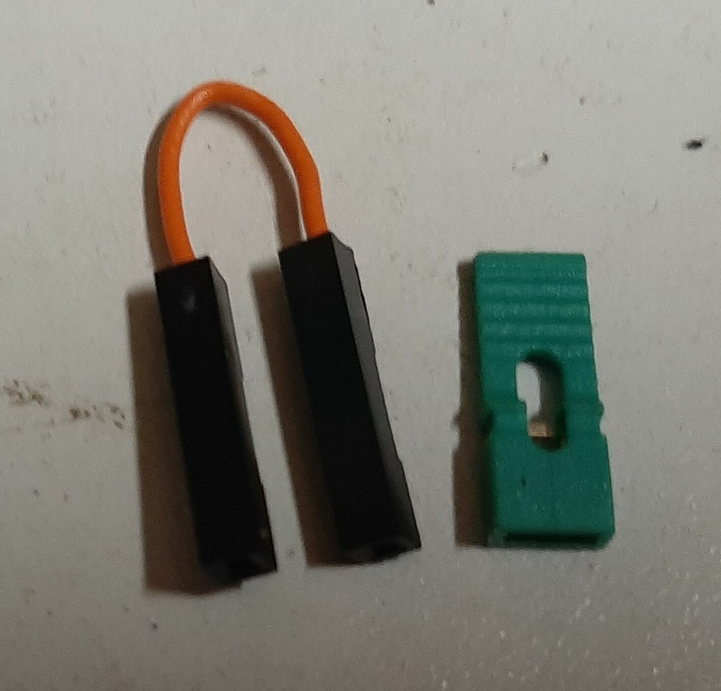
The short wire goes between U6A and the first pin on U6B and the link ( or switch cable ) goes on the other 2 pins to select the lower bank , if the link is left off the upper bank is selected.
Here it is fitted ( with some more appropriate labels ).
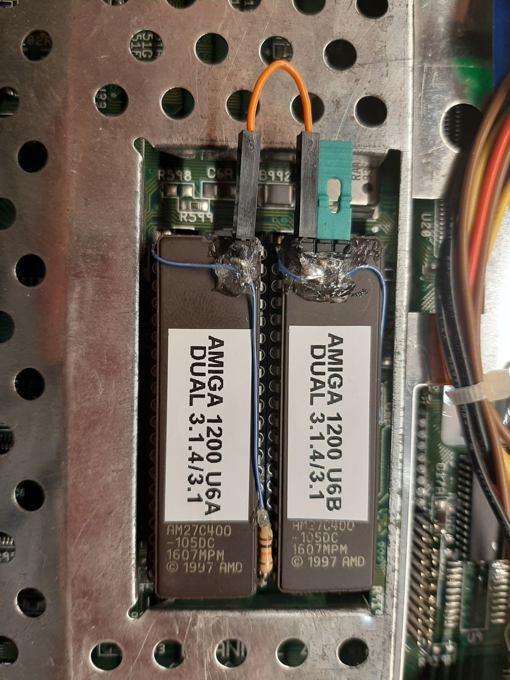
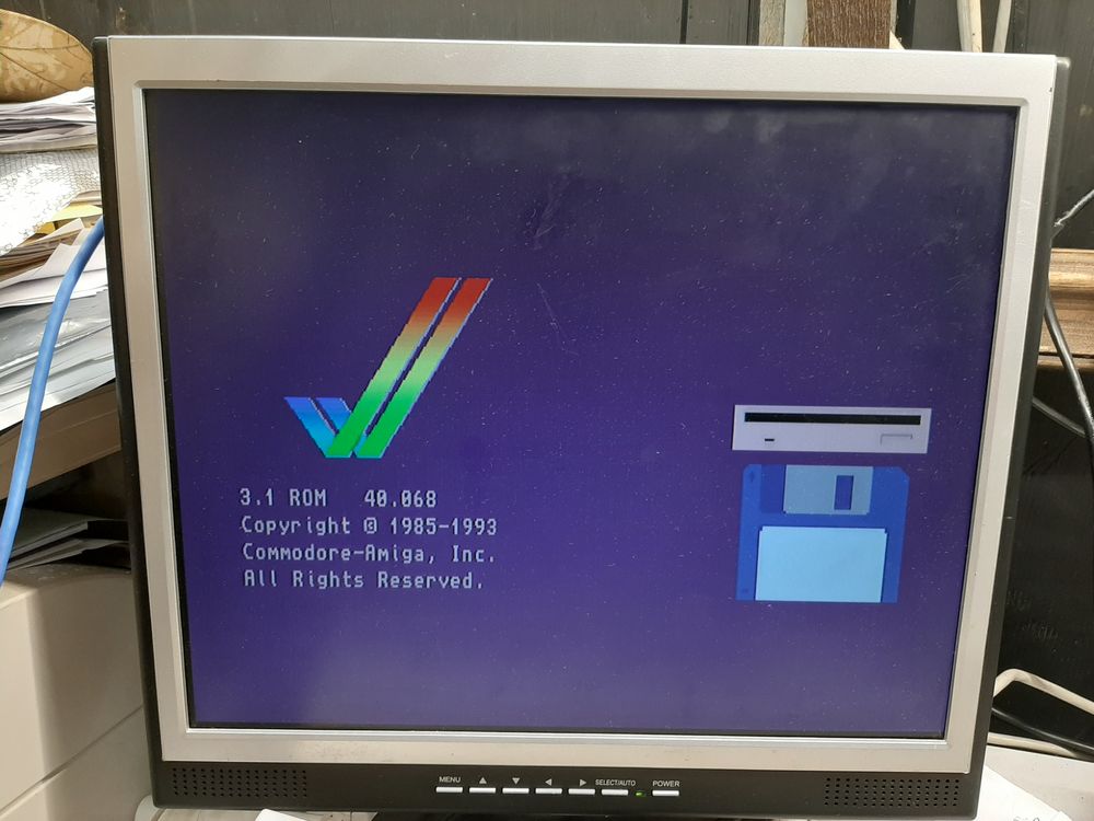
Booting lower bank ( link on ).
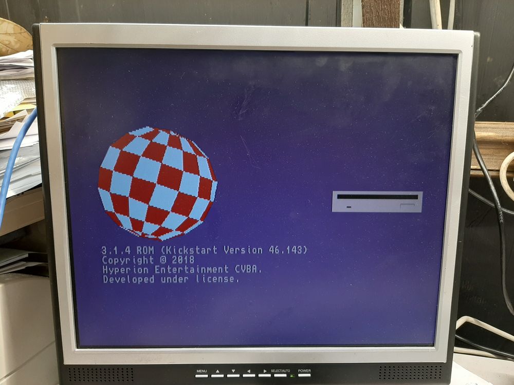
Booting upper bank (link off ).
Remember you cannot change the kickstart with the AMIGA turned on , it will crash. Always turn off before changing the kickstart.
I have an Issue 2 pack - so if it works I'll send the details and you will have a…