
Please note after extensive testing it would appear that the 20MHz mod is only working for one internal drive . The short cable allows for communication at this speed . However if you wish to use external devices , then the Xtal should be reduced to 16MHz . This still gives a speed increase over the 14MHz mod .
When doing the 14Mhz mod on my A590 I noticed that the controller chip is capable of 20Mhz , so why not do that instead!
First of all how I did the 14Mhz mod.
Updated the roms to V7.0 ( U12 and U13 )
Removed U6 ( 74LS86 ) and fitted a socket , so that pin 13 can be left out of the socket.
( This avoids a track cut on the board! )
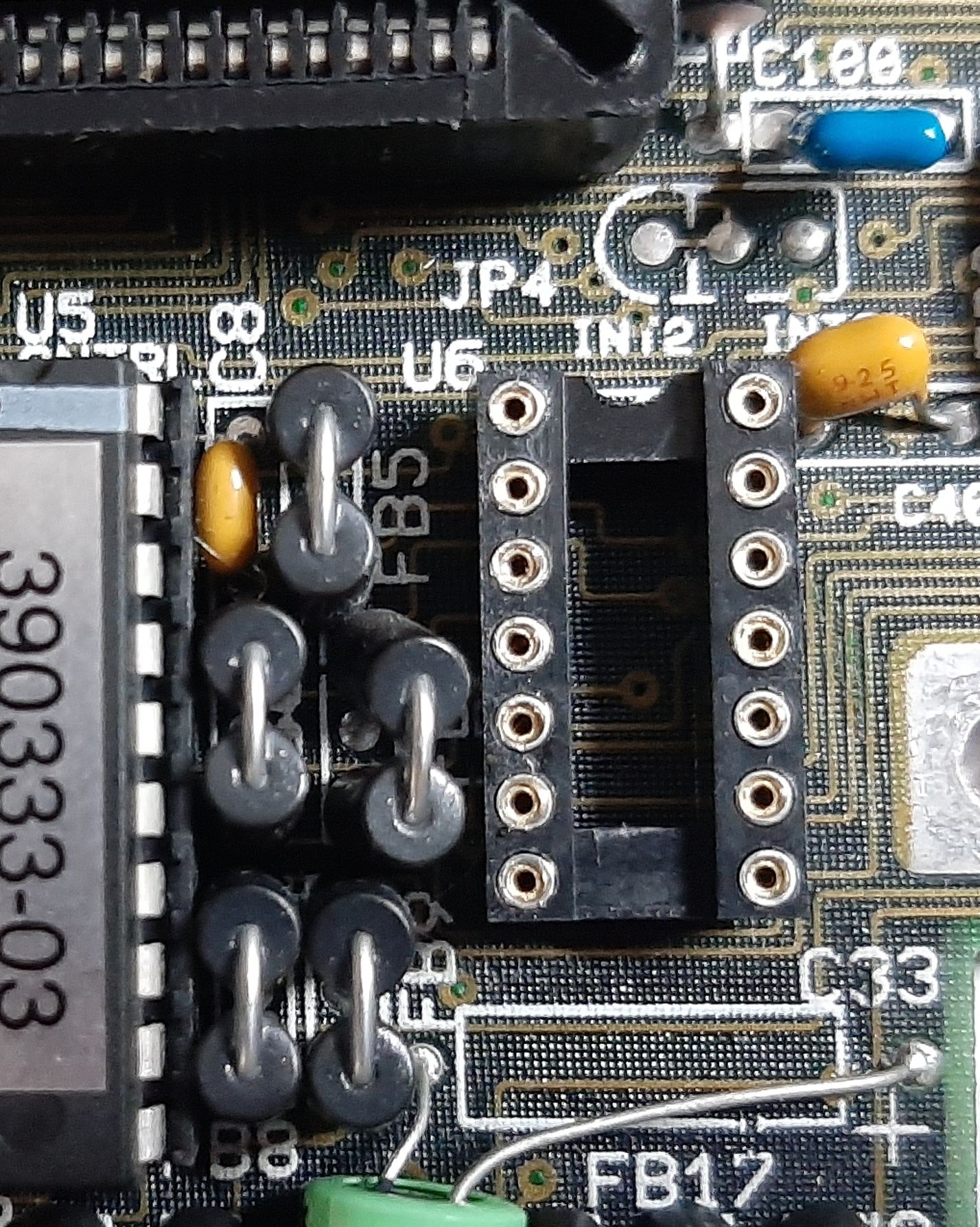
Fit a link across the 74LS86 from pin 6 to pin 13 and leave pin 13 OUT of the socket.
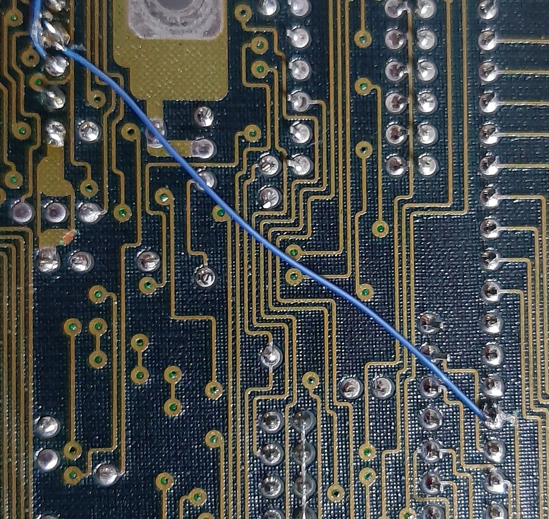
Fit a link from 74LS86 pin 12 to pin 9 onthe underside of the board.
Cut the track at Pin7 of the 33C93A.
Fit a link from pin 11 of the 74LS86 to pin 7 of the 33C93A.
That is it 14Mhz mod done!
Now let us go to 20Mhz
If we look at the 14Mz mod , it is generating a 14Mhz clock signal from XOR’ing the 7Mhz clock with the CDAC signal and feeding it to the clock signal 33C93A controller.
As the 33C93A we need to use for the 14Mhz mod is capable of 20Mhz (unless it is the AM33C93A-16 this can only handle 16Mhz ) all we need to do is remove the 14Mhz mod ( good job i socketed the 74LS86 (you could just remove the link from U6 to U4 and repair the cut at U4 and just leave the rest as is!) ) and find a good point to mount an 20Mhz oscillator module to feed the clock of the 33C93A.
You will need :-
1 x 20Mhz oscillator module
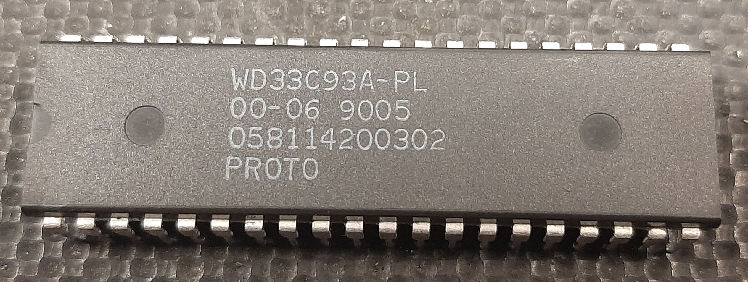
the WD33C93A version that is of the right batch see ‘A590 14mhz mod‘ posts on the web ( or the AM33C93A-20 )
This is the one that is running at 20Mhz for me!
And a patched version of the U12 rom for the A590/2091 that sets timings the file is available to download here A2091O14.zip
Created by SpeedGeek on the English Amiga Board
and that is it!
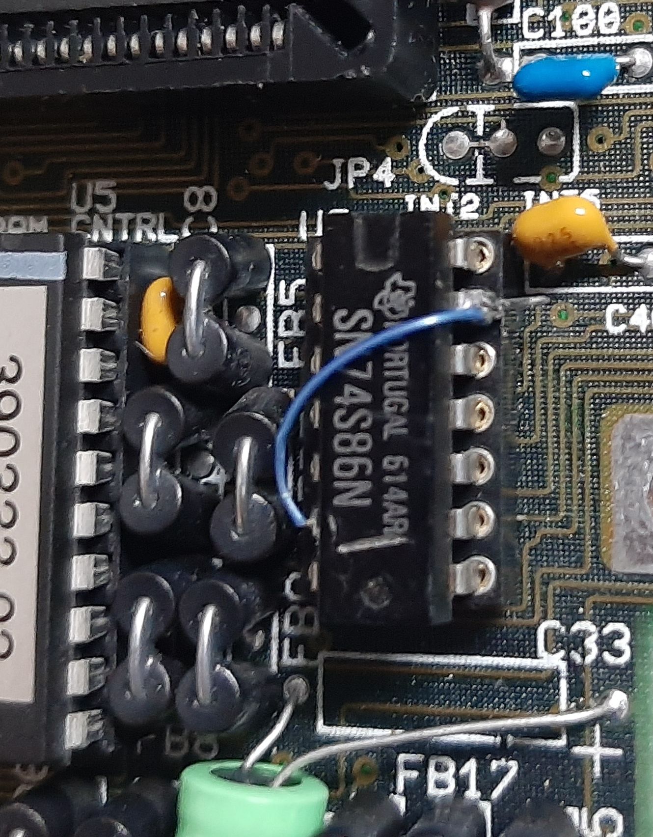
Right , time to clean up the mod at the ls86.
Remove the top link and fit all pins in the socket.
Remove all the bottom links.
Repair the track cut.
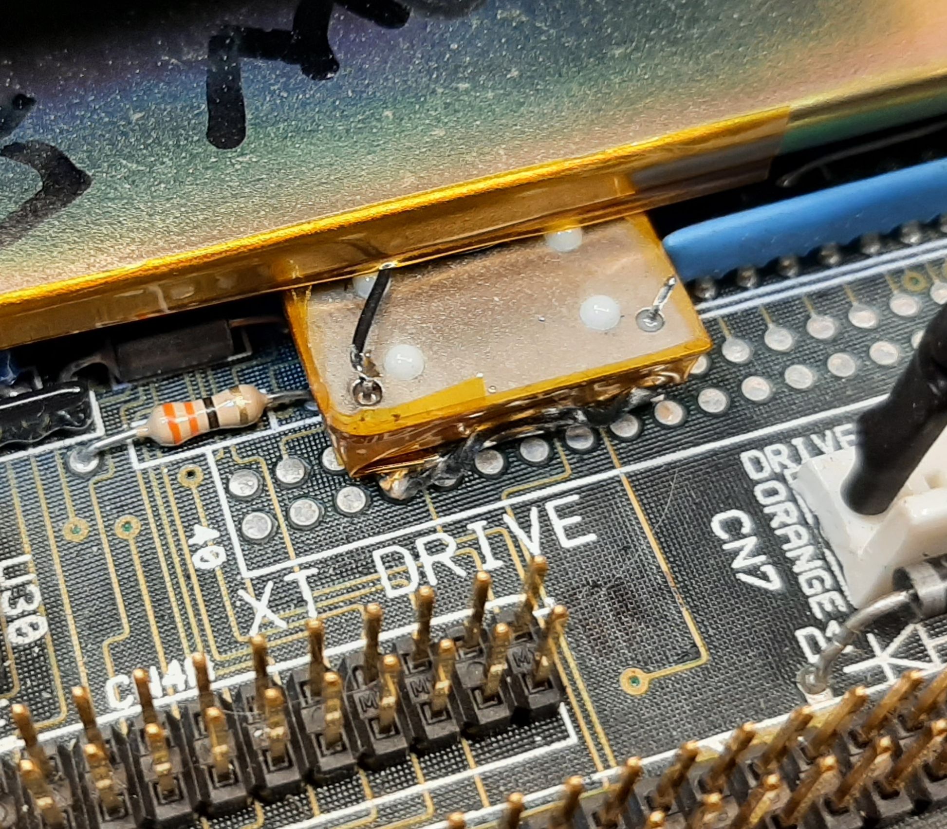
Now where to put the oscillator?
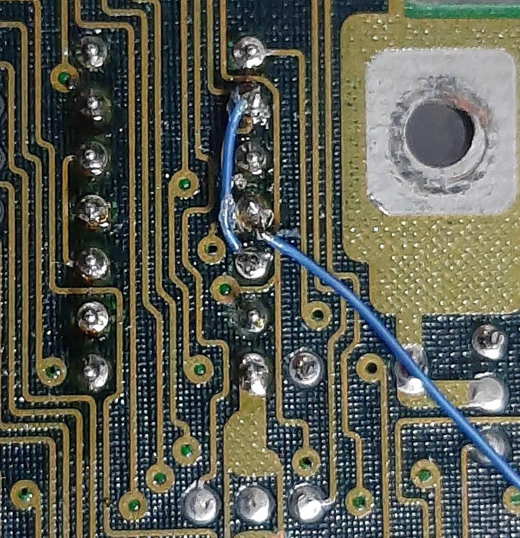
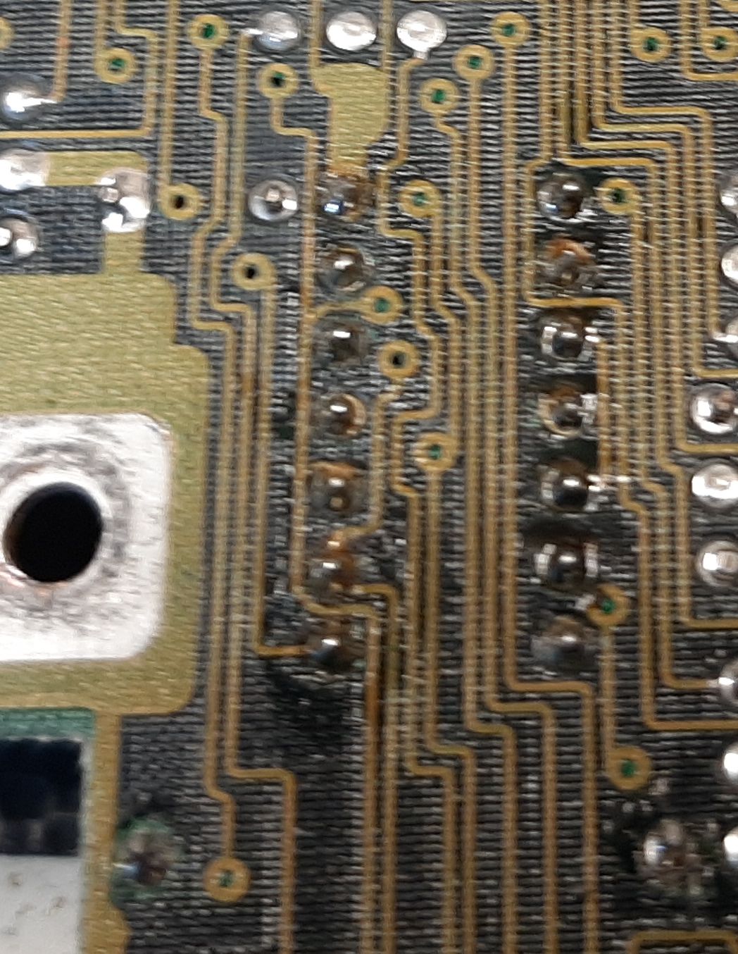
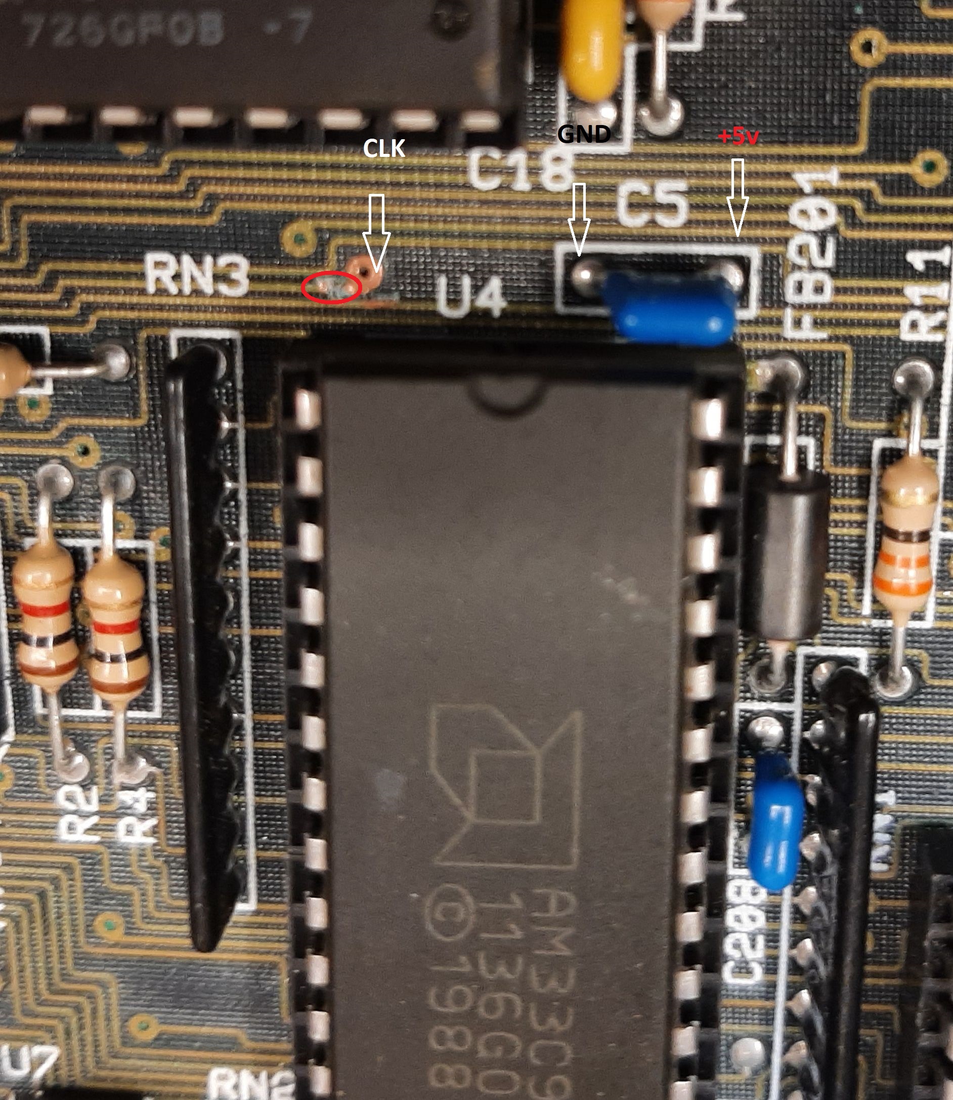
If you follow the track that was cut you will come to a Via ( plated through hole ) at the top of the 33C93A .
There is also a smoothing cap for the chip there that has +5v on one side and GND on the other.
This is all we need for the crystal oscillator module.
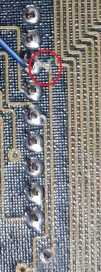
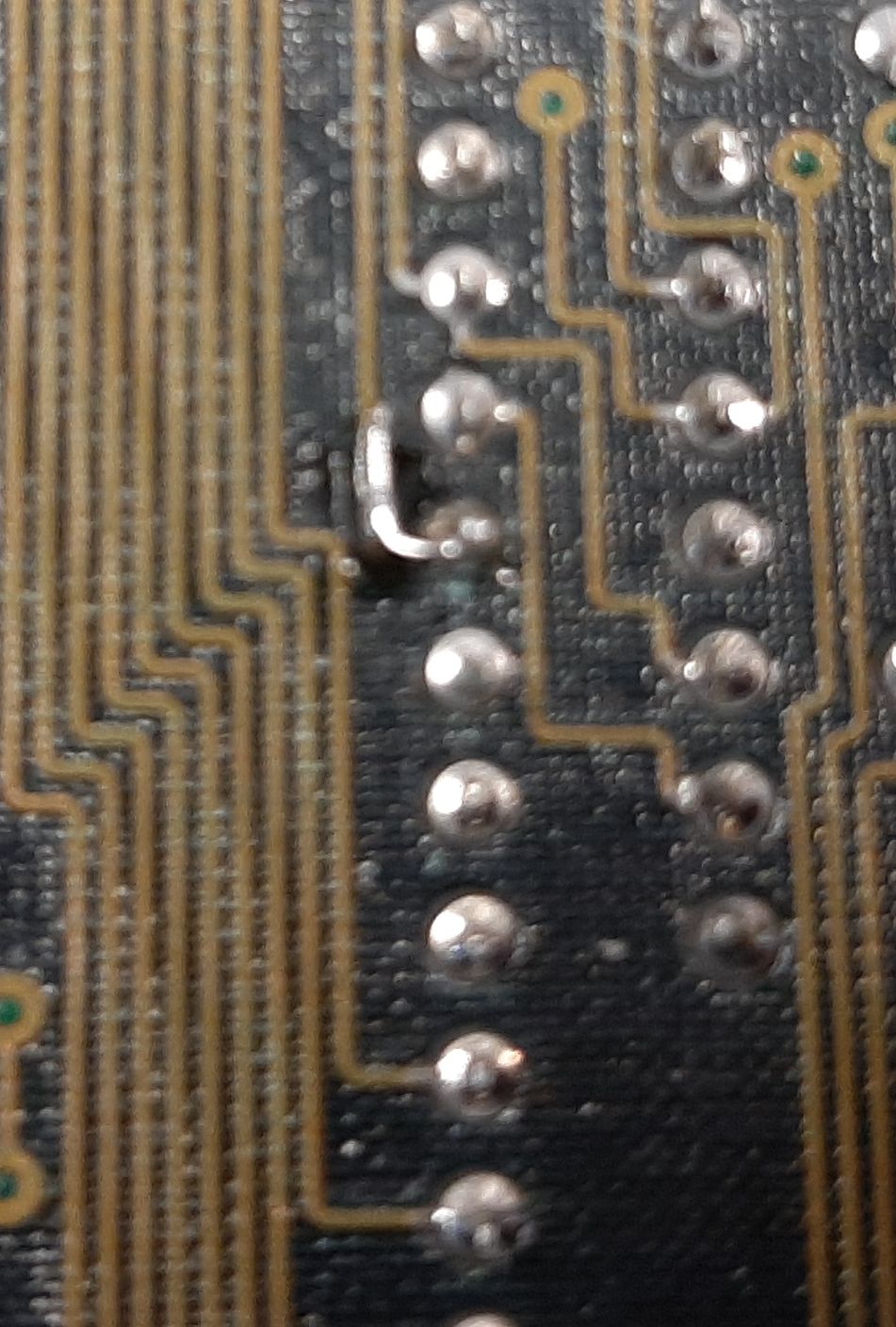
Now a track cut on the top side of the board to seperate the 7Mhz clock from the 33C93A , yes we are cutting that track again but in a different place.
Be very careful with the track cut ( in the red circle ) as the tracks are close together at this point.
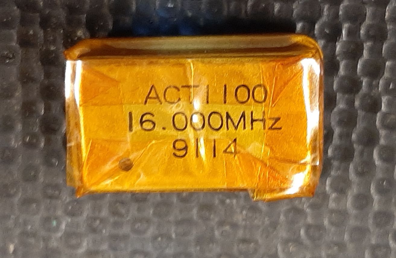
Wrap the oscillator in kapton tape to stop any shorts.( This is the 16Mhz one that i used to prove the theory. )
fix in place with some hot glue and wire it up.
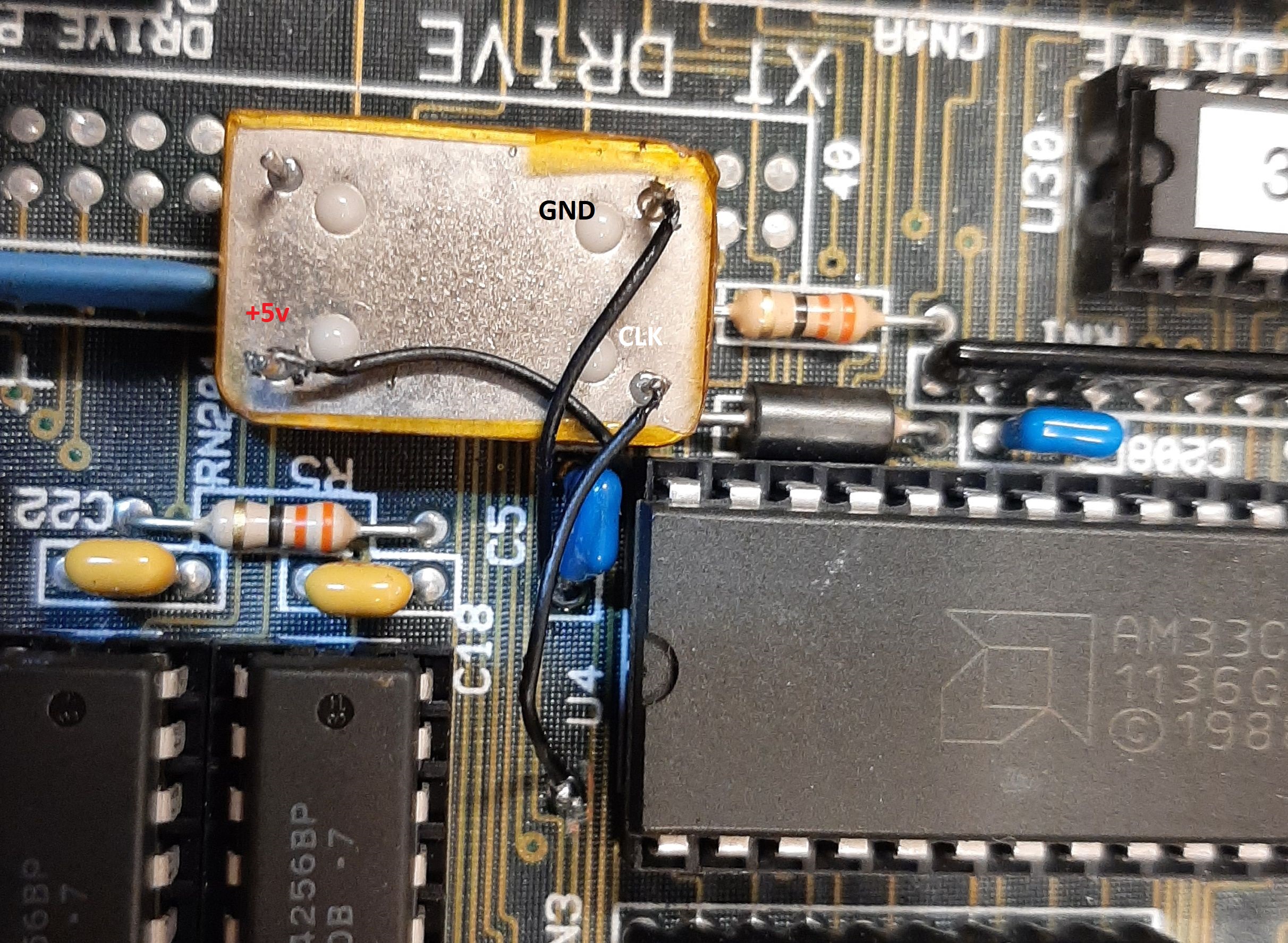
Put some kapton tape on the heatshield.
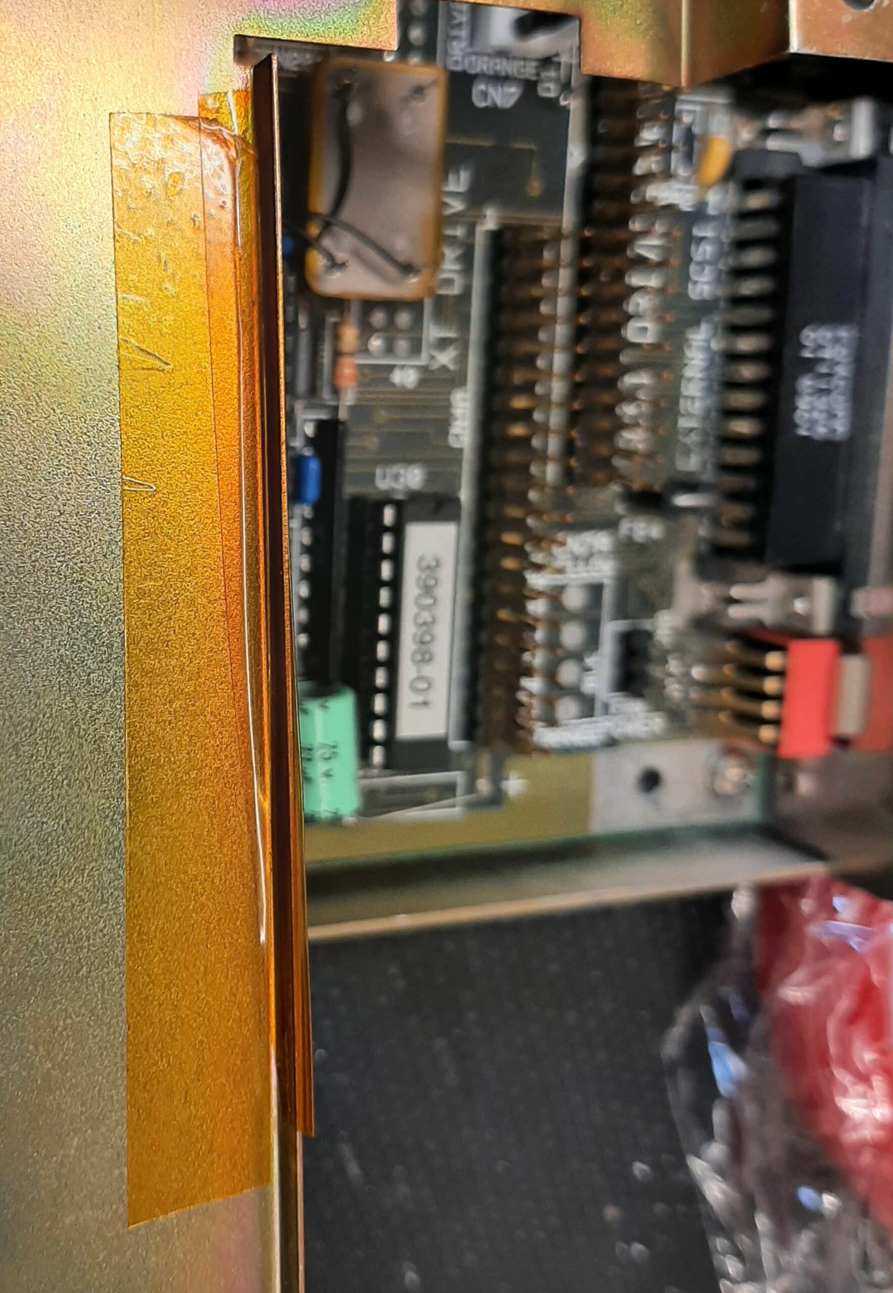
Just in case you were wondering ‘ why the kapton tape’!
Replace the V7.0 ROM at U12 with the patched version ( the only change is in U12 , V7.0 U13 can stay where it is! ).
Your SCSI interface should now be running at 20Mhz!!! ( check U4 pin 7 with an oscilloscope ).
On an A500+ with 2Mb of chip ram and the 2Mb fast ram on the A590 SYSINFO is reporting scsi drive speeds in excess of 1.7Mb/s.
With the 14Mhz mod it was giving 1.4Mb/s with the same drive.
If you do not want to go through all this , then you can , of course , just use the stock roms and a 10MHz oscillator . This will have your 33C93 running at it’s stated maximum speed . The stock ROM’s have the clock divisor set to divide by 2 and 10Mhz divided by two = 5Mhz which is the stated maximum clock speed for the 33C93 .
Time to debunk the myth
The WD33c93A actually has a clock speed maximum of 5Mhz but the clock has a divisor which can be set . The stock rom’s set the divisor to 2 and as the amiga is feeding it with 7MHZ this becomes 7Mhz/2 = 3.5Mhz . The 14Mhz rom changes this to divide by 3 , which gives 14Mhz/3 = 4.66Mhz . With the 16Mhz I am slightly overclocking the chip 16Mhz/3 = 5.33Mhz . The 20Mhz version leaves the divisor at 3 , so 20Mhz/3 = 6.66Mhz , a big overclock but unstable with long cable lengths .
The best for the chip would be to use a 10mhz oscillator module and leave the original roms that gives 10Mhz/2 = 5Mhz The actual stated maximum for the chip .
I have an Issue 2 pack - so if it works I'll send the details and you will have a…