The Idea for this project came from my building of a Spitfire 500 accelerator .
The Spitfire 500 is a 14MHz accelerator for the AMIGA 500 computer and has 8MB of fast ram on board , and an IDE interface . It is a good board , but lacks any indication that the IDE is working when accessing the on board IDE interface .
So , what can we do about this ? The best option is probably to use the Floppy drive access LED , so that it will show IDE or Floppy accesses .
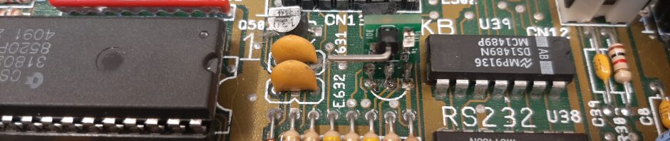
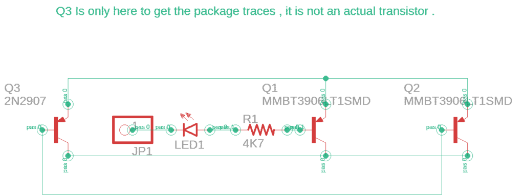
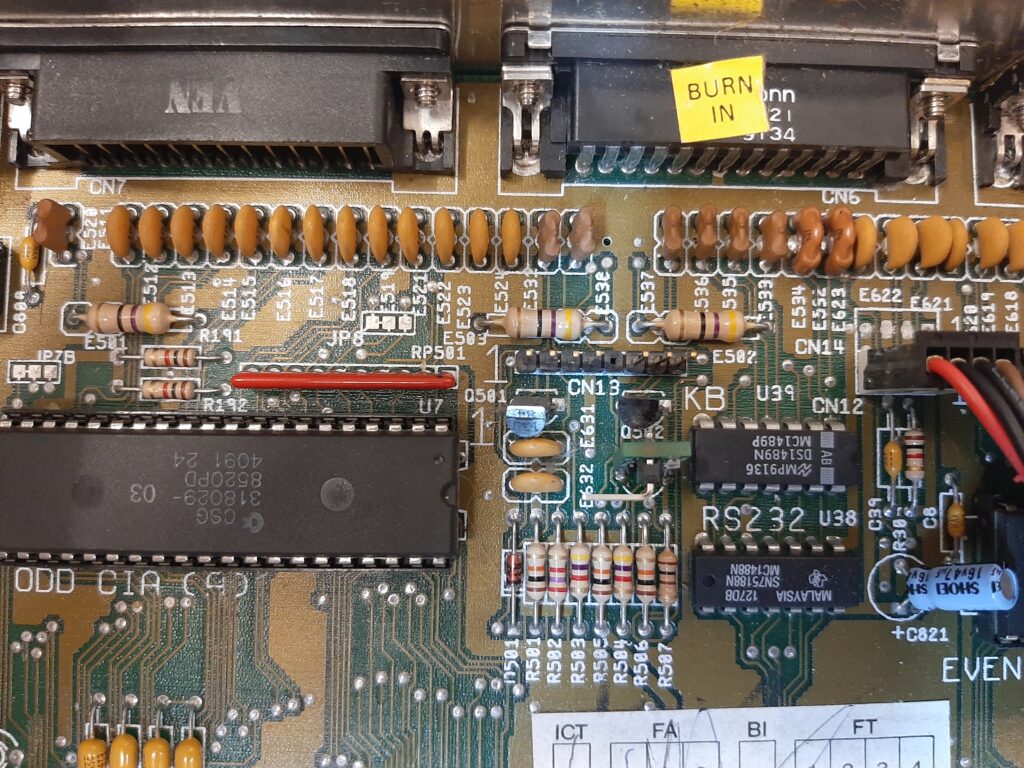
On the schematic diagram for the AMIGA it uses Q503 ( 2N3906 PNP transistor ) to drive the floppy access LED . The signal comes through a 4K7 resistor to drive the base of the transistor , and light the LED . The most important thing is that this is an active-low signal , and on the IDE interface there is a pin marked /ACT . It is also an active-low signal , so I could use the same circuit as on the AMIGA to do the job .
A quick search on line showed that there was a surfacemount equivalent of the 2N3906 and that was the MMBT3906 in an SOT23 package . If I could make a pcb with two of these transistor’s and drive the base on the second one from the /ACT signal it could replace the Q503 on the AMIGA and drive the LED from either signal .
So order some MMBT3906’s and some small smd resistors ( 0603 ) size , lets keep the board as small as we can , so that it won’t be obtrusive and looks almost like it should be there . Ok I know what I am using so I designed the board while I was waiting for the parts to arrive .
It takes a long time to get things from china ( actualy it is about 10 days at the moment ) , but when you are anticipating their arrival it seems like months .
Finally they arrived , and I bodged a prototype together . The floppy LED worked , but the IDE signal was holding it on all the time . Why ??? Then it struck me , I was using a compact flash to IDE adapter as a Hard drive , they run on 3.3v not 5v . the highest the signal could go was 3.3v and I was using 5v . I needed to lose 2v somewhere , an LED has 2v forward voltage drop , and a friend had asked if i could put an LED on the board . There we go , an LED . Now it will work with both 3.3v and 5v devices .
Just as an extra note , on a 44pin IDE/ATA interface ( and a 40 pin ) the /ACTIVE pin is pin 39 . This is the one that would connect to the IDE/FLOP to give a visual of hdd activity on the floppy access LED .
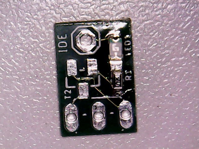
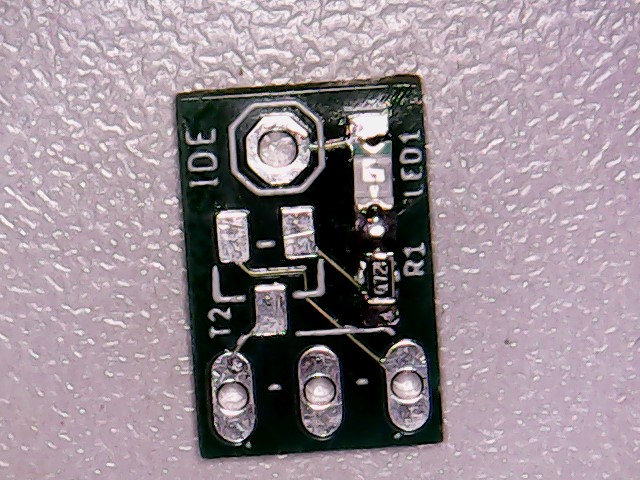
Here is the result .
As normal , PCB’s are avalable from PCB way .
And OSHpark .
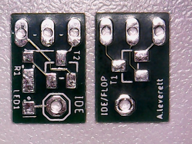
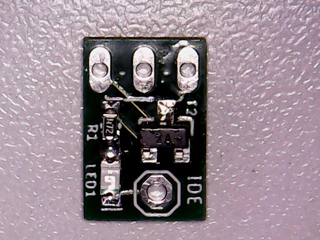
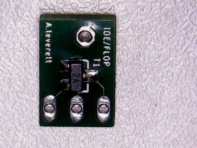
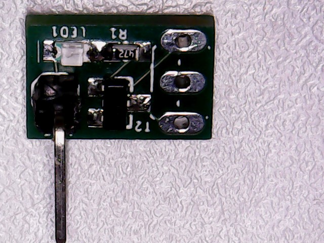
This is apicture of the top and bottom of the pcb , be aware this board , and the components are tiny .
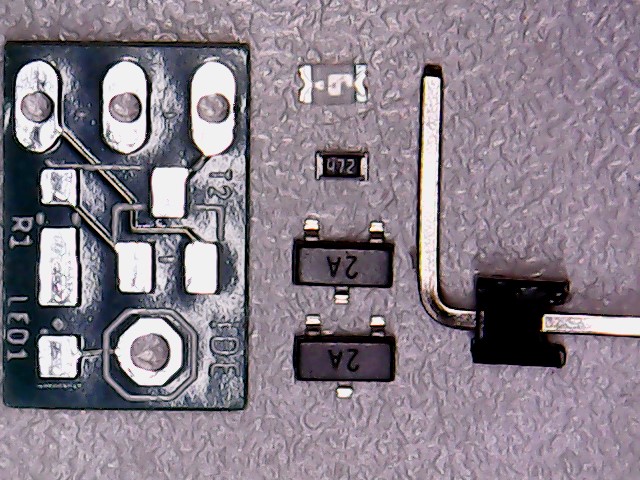
This is everything you need to assemble the board . I have used a blue LED but you can use any colour you like as long as it is 0805 size .
2x MMBT3906
1x 0805 size LED
1x 4K7 resistor 0603 size
90 degree header pin
PCB .
Start by tacking the oposite ends of the LED and the resistor on the board , when you solder the junction between them , it will solder both . The cathode of the LED has a touch of green colouring .
Like this .
Then the center leg of the transistor , this holds it in place so you can solder the other two .
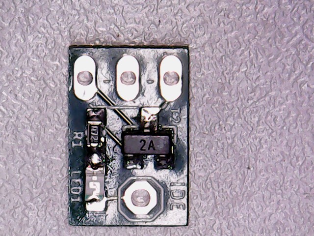
solder and a quick clean and all done this side . Time to turn over .
Solder the other transistor on here and we just need to fit the header pin .
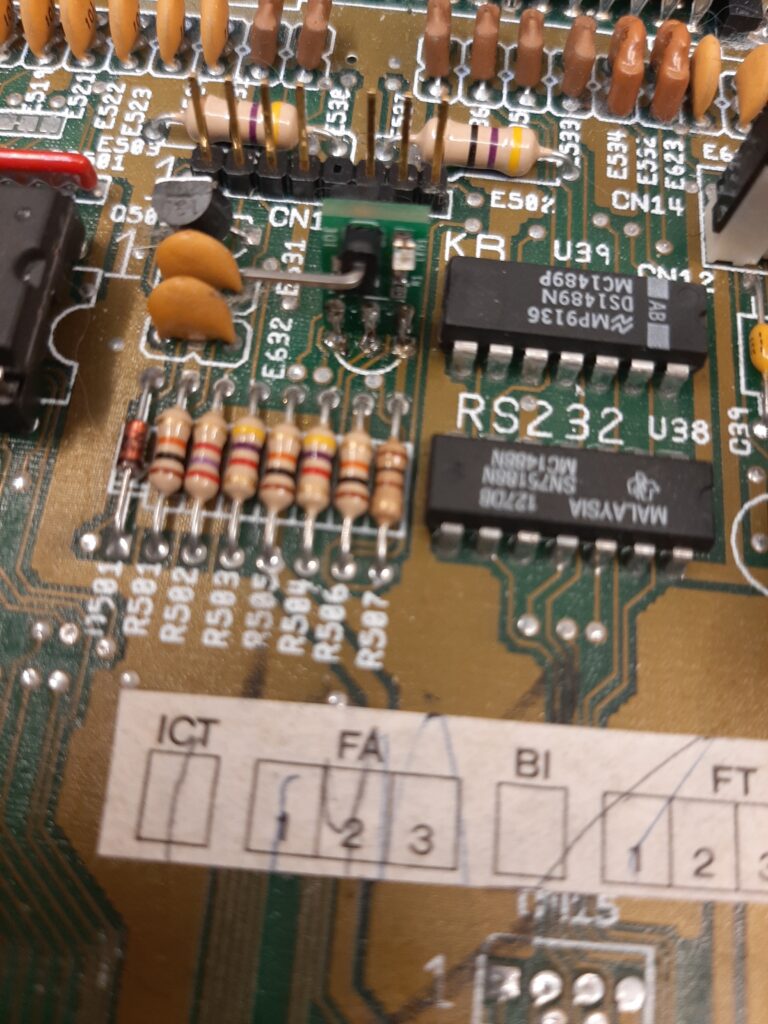
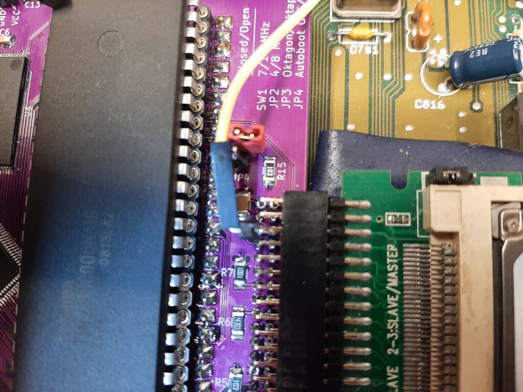
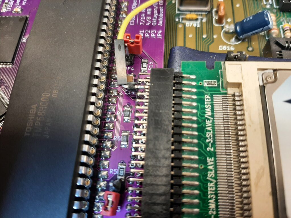
All done , now to fit it in the A500 , ( mine is the plus but it is in the same place ) .
You can remove the board from the A500 and de-solder the transistor properly , or you can take the easy way …. Cut the legs off of the transistor and remove one at a time from the hole , then clear the solder out of them , either with braid or a solder sucker .
I used resistor leg trimmings to make the legs to fit mine in my A500+ . If there is enough of the transistor leg left , you could solder straight to those !!!
Please note , the LED faces the front of the A500 .
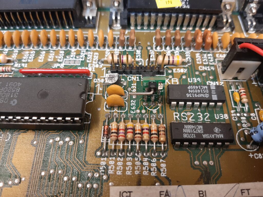
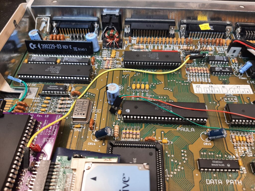
As you can see it is small , neat , unobtrusive AND has an LED all boxes ticked and fully working .
Now to think of another project ??????
You can get the PCB from PCBWay .
And OSHpark .
It could be used for any active low signal in the amiga , so could be used to monitor , for example , the /reset signal . Therefore could be handy for repairs as well .
If you are desperate for one , then please get in touch . I ended up buying 50 boards and i might still have some left .
Do you have a video you can share with us of this working? I love the fact that this design is so unobtrusive. It’s a little more work for installation for some but I think it’s definitely much more sleek. Thank you for designing something based on a new design.
Yes I think I have a video to put on , thank you for the suggestion .
Levoman was kind enough to sell me several units, they are well designed and work perfectly.
Thanks for sharing this with the retro Amiga community Levoman..