A590 PSU schematic
The A590 is a bit of a confusing power supply , as it looks just like an AMIGA power supply but without a power switch . It also has a round Din type plug on the lead , instead of the square AMIGA style connection .
As a lot of people have been asking about the PSU for the A590 i thought i would take mine apart and reverse engineer a schematic diagram of it.
First the PCB wiring.
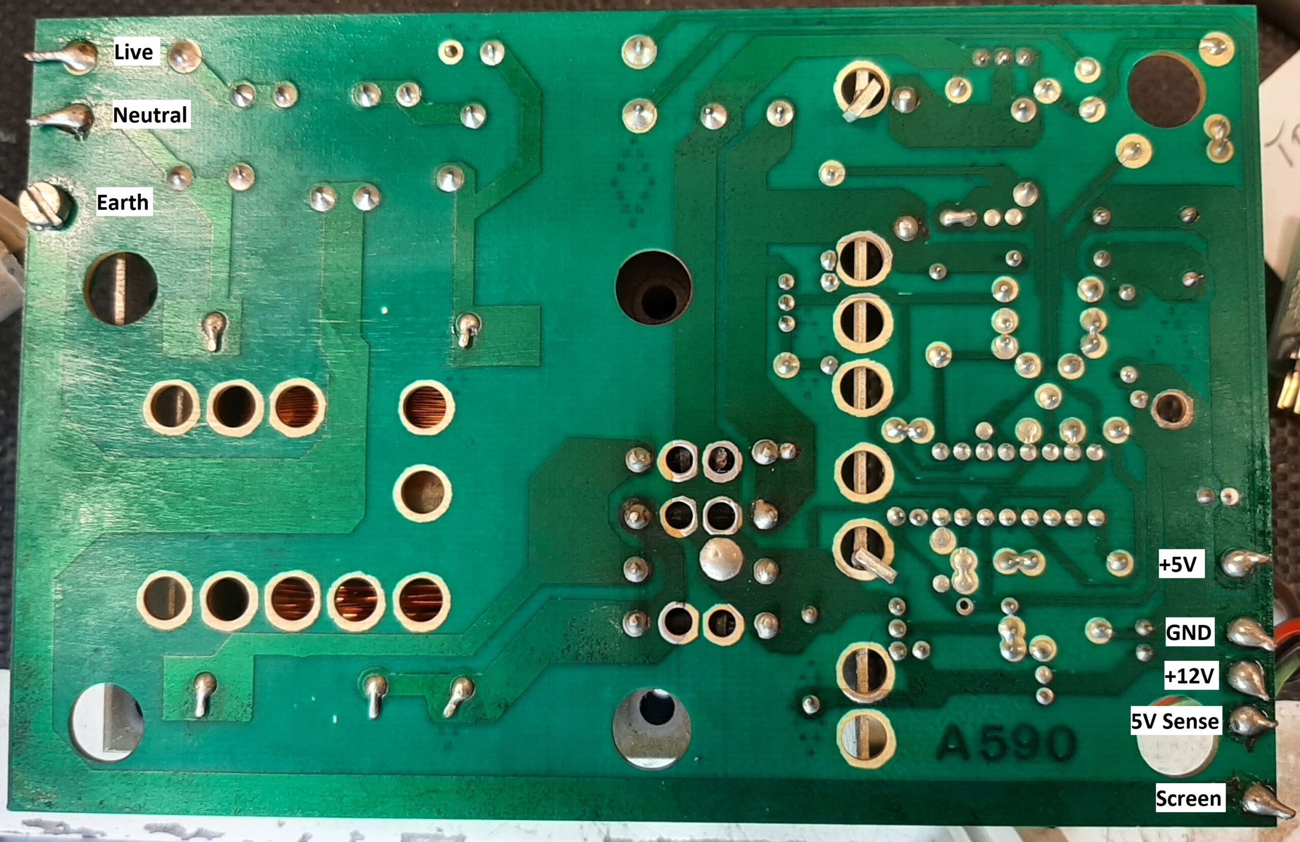
On mine the AMIGA connector colors are as follows.
Brown = +5v
White = GND
Red = +12v
Black = 5V sense
Green = Screen ( Directly connected to the earth input )
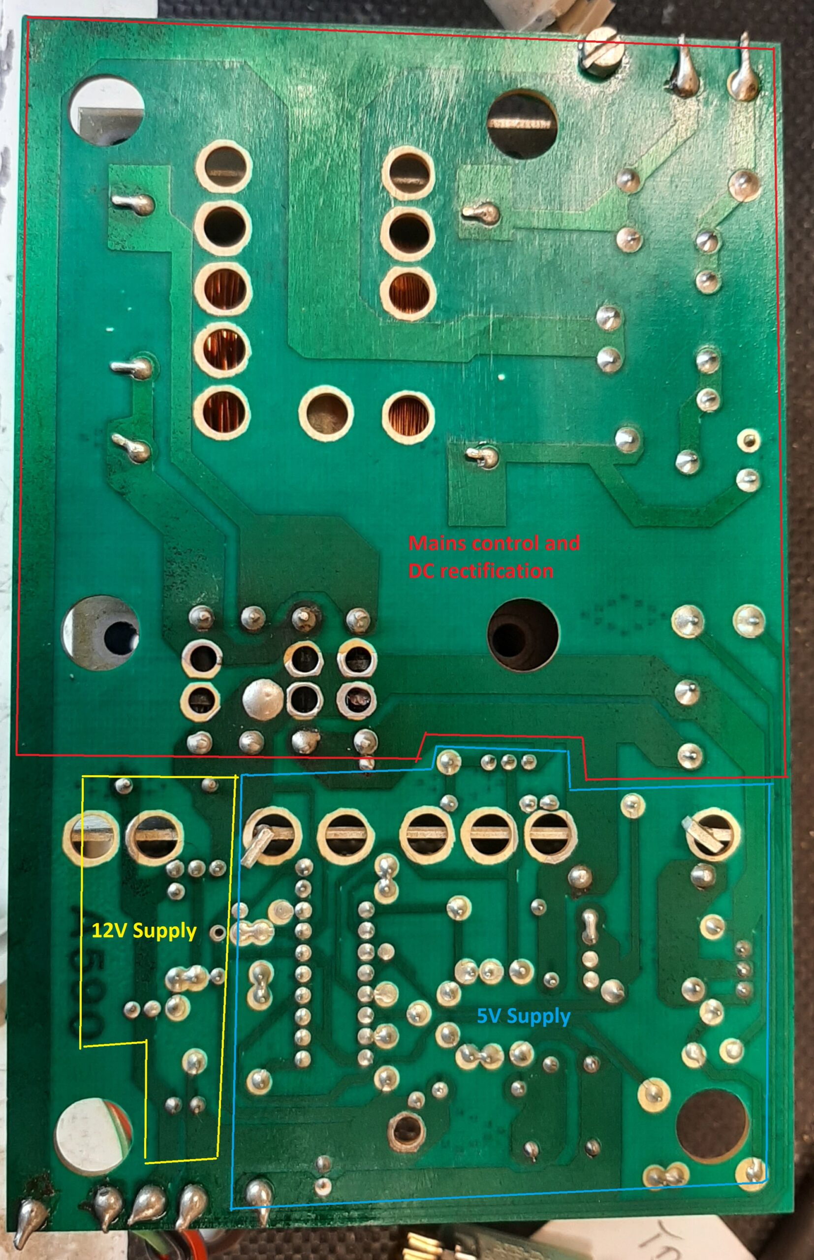
I have broken the schematic into three parts:-
1. mains control and DC rectification
2. 12V Supply
3. 5V Supply
Part 1 Mains control and DC rectification .
This contains the bit that most people ask about ‘ what is the 5v sense for? ‘.
Here is a schematic for this section .
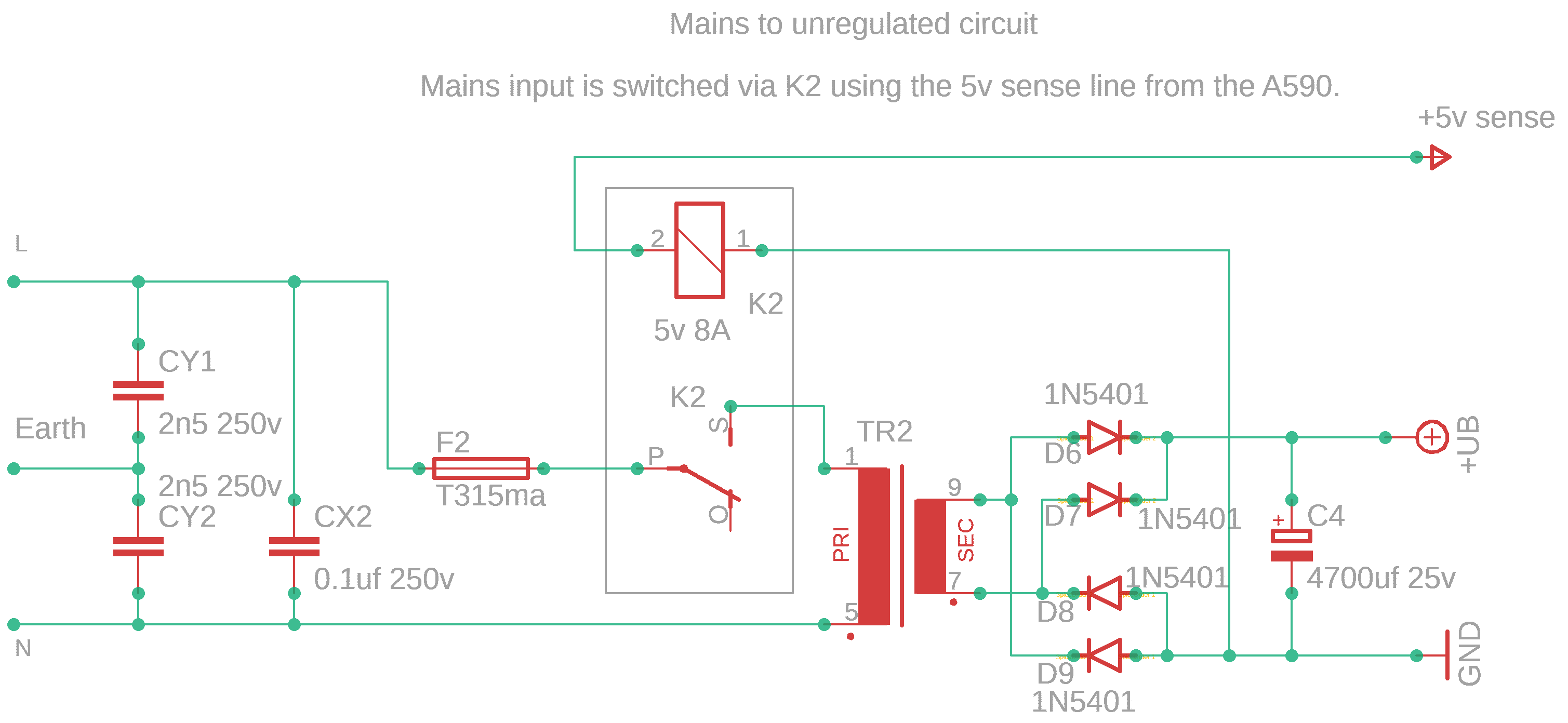
Answer : – The 5v sense line ( actually the 5v supply from the AMIGA sidecar connector ) operates the relay to turn the power supply on .
The output of the transformer is 18.3v a.c. under load.
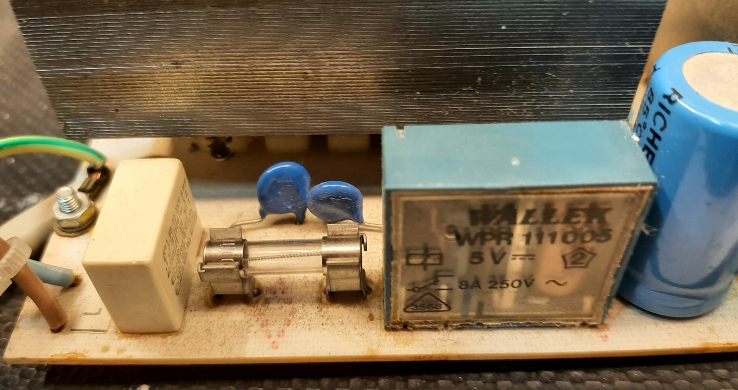
Here is a picture of the relay and associated components.
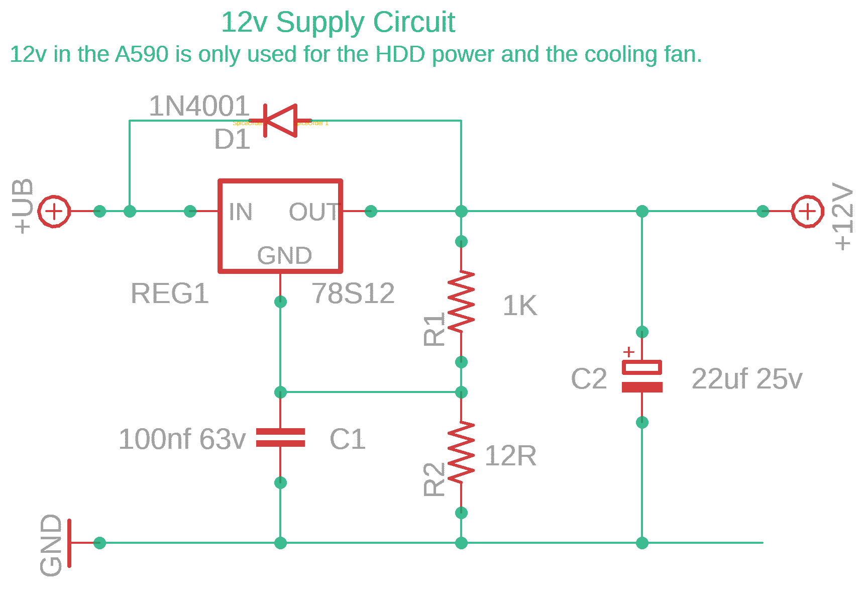
Part 2 12V supply.
The 12v supply is quite a basic circuit.
Here is the schematic for it.
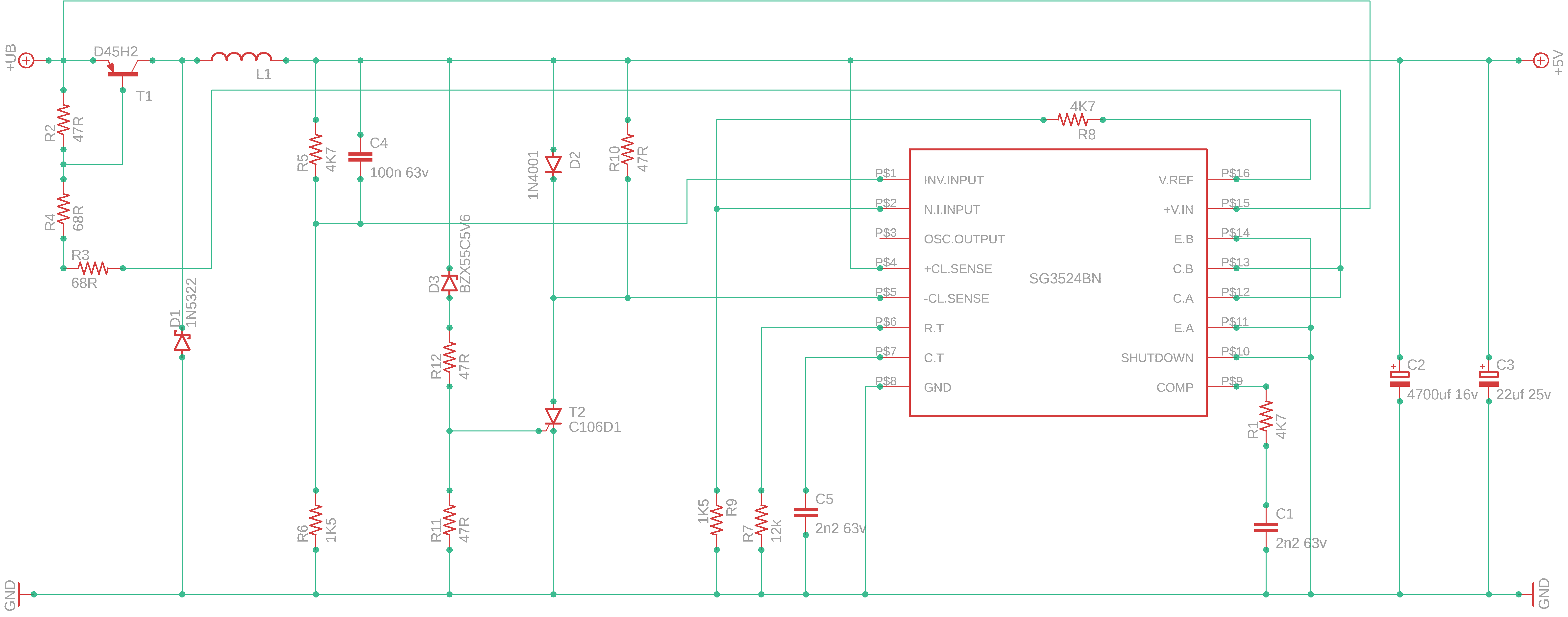
Part 3 5V supply
The 5V circuit is a bit more complex , using a PWM control I.C. to create a switch mode supply.
Here is the schematic for it.
I have tried to include all values , where possible.
Unfortunately I cannot do this for the transformer or the L1 inductor.
If you find any discrepencies , please contact me with details so that i can rectify them!
I have an Issue 2 pack - so if it works I'll send the details and you will have a…