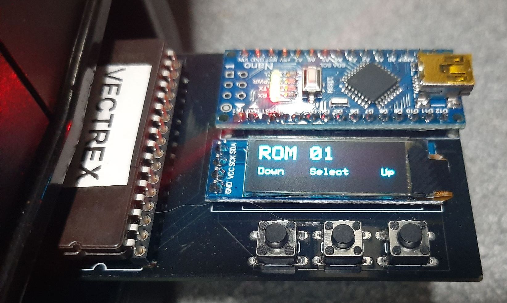
The Home of the VECTREX DIY Cart+
Project to create an easy to build version of the vectrex selectable rom cartridge.
The idea behind this project came from the multitude of multi-game cartridges for the vectrex.
Goals:-
display rom no.
no dipswitch selectors
minimal parts
easy to build with little knowledge
From this I put this list together:-
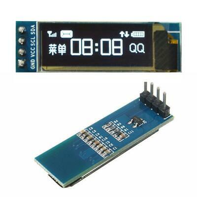
Display I2C oled 128×32 display
Arduino NANO to replace the dip switches with an easy to select menu
up button , down button and select button
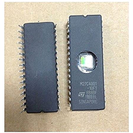
eprom for storing roms
27c4001 will store up to 64 8kb images.
Function :-
The arduino supplies the address lines for the eprom above the 8kb or 32KB boundary mark ( A13 upwards for 8KB and A15 upwards for 32KB ).
Holding the up or down button will cause the display to count in that direction ( with wraparound , 1 becomes 64 and 64 becomes 1 depending on direction ).
The amount of ROM’s on the cartridge can be set so the count will not go over that. (RomMax integer in the software ).
The address is only applied after hitting the select button at which point the console needs to be reset to load the rom or , if you use my menu program it will reset the console before setting the address.
I was hoping that the cartridge port would have a reset line that could be used but sadly not so the reset has to be manual meaning the system will crash after hitting select.
After asking for suggestions on https://vectorgaming.proboards.com/ i have written my first VECTREX program with rom No. and title as the first image on each of the cartridge images i create.
The parts:-
1x 470R resistor 1/4W
![]()
I2C Oled display 128×32
Arduino NANO ( the 168 or 328 cpu version will work )
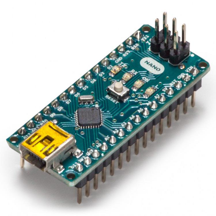
If you get it in kit form there is no need to solder the 6pin icsp header.
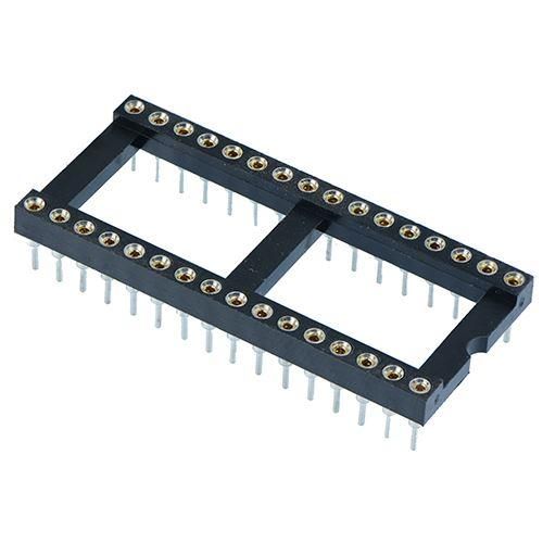
32 pin dip ic socket .
27c010 for 15 8KB roms or 3 32KB roms .
27c020 for 31 8KB roms or 7 32KB roms .
27c4001 ( or 27c040 they are the same ) for 63 8KB roms or 15 32KB roms .
27c080 for 127 8KB roms or 31 32KB roms .
( they can all actually hold one more because i have allowed for the menu rom image as No. 01. )
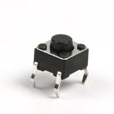
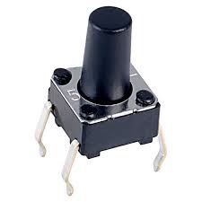
3 x push button ( longer ones are available if you wish to 3d print a case )
and , of course , the PCB
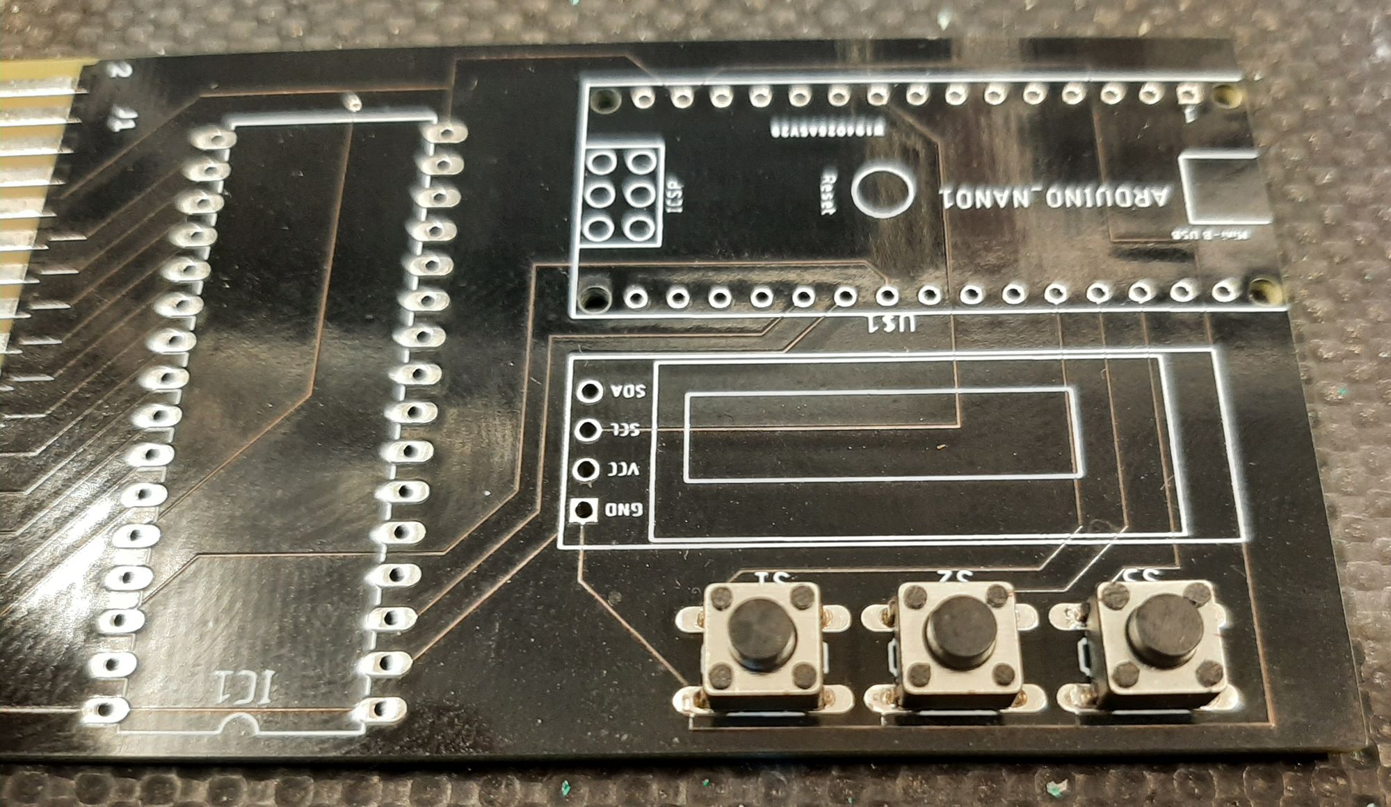
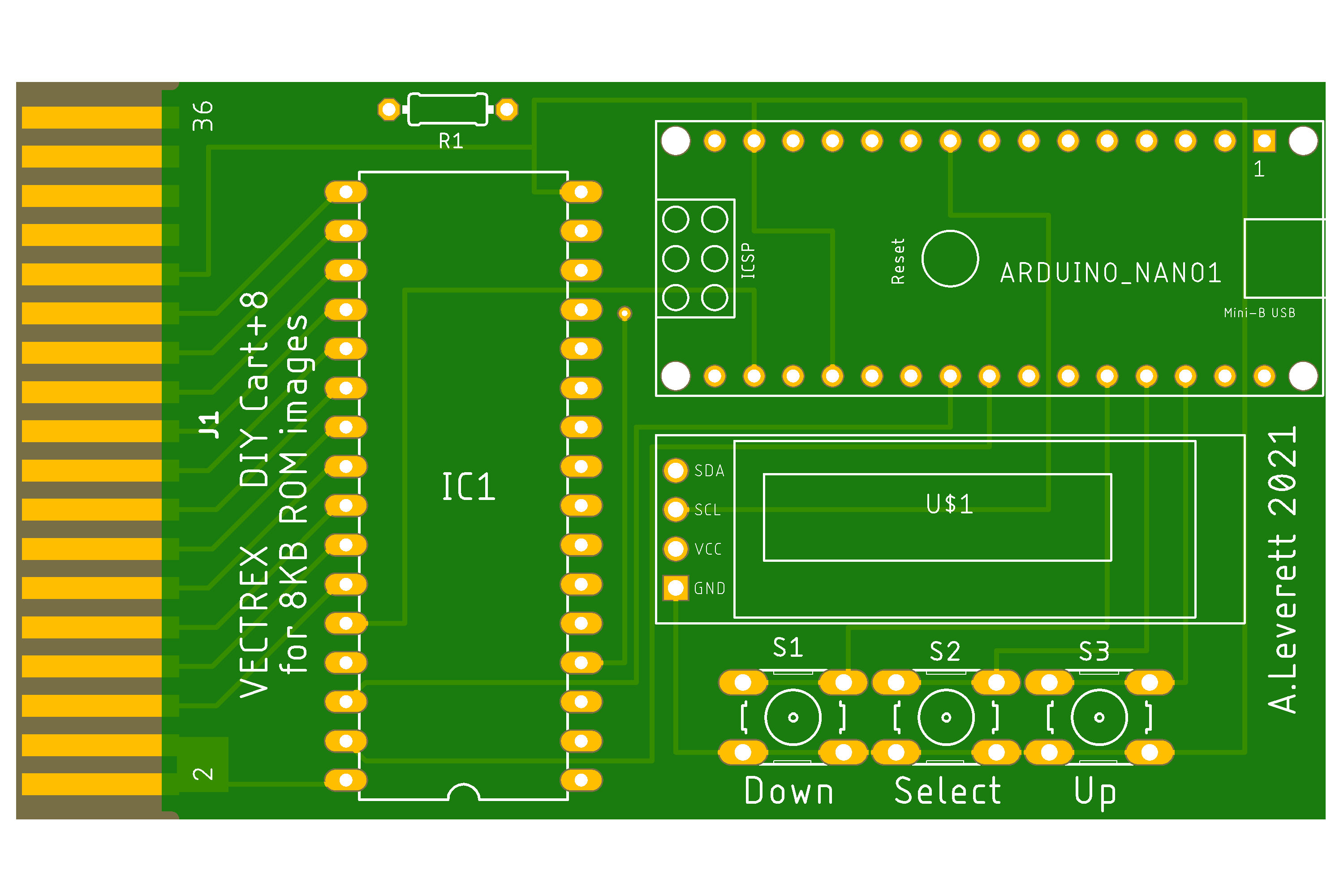
This is the protype PCB , you will be using the final version .
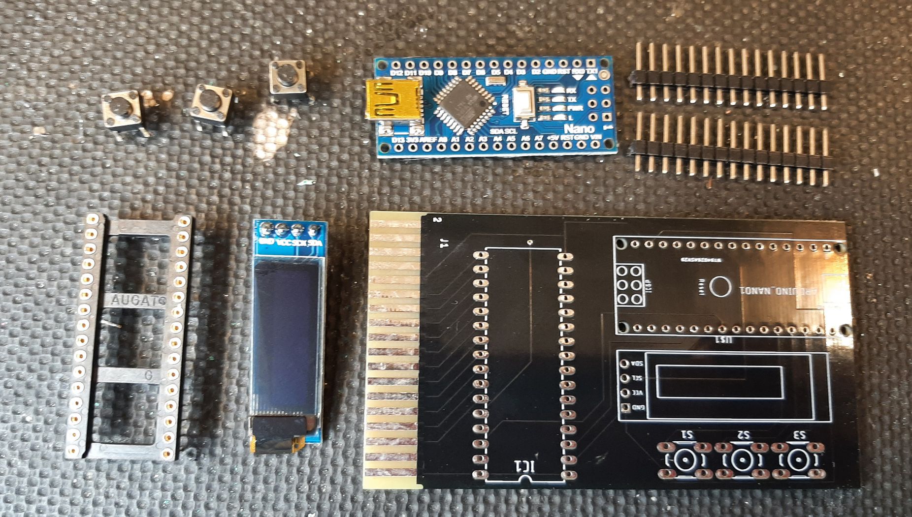
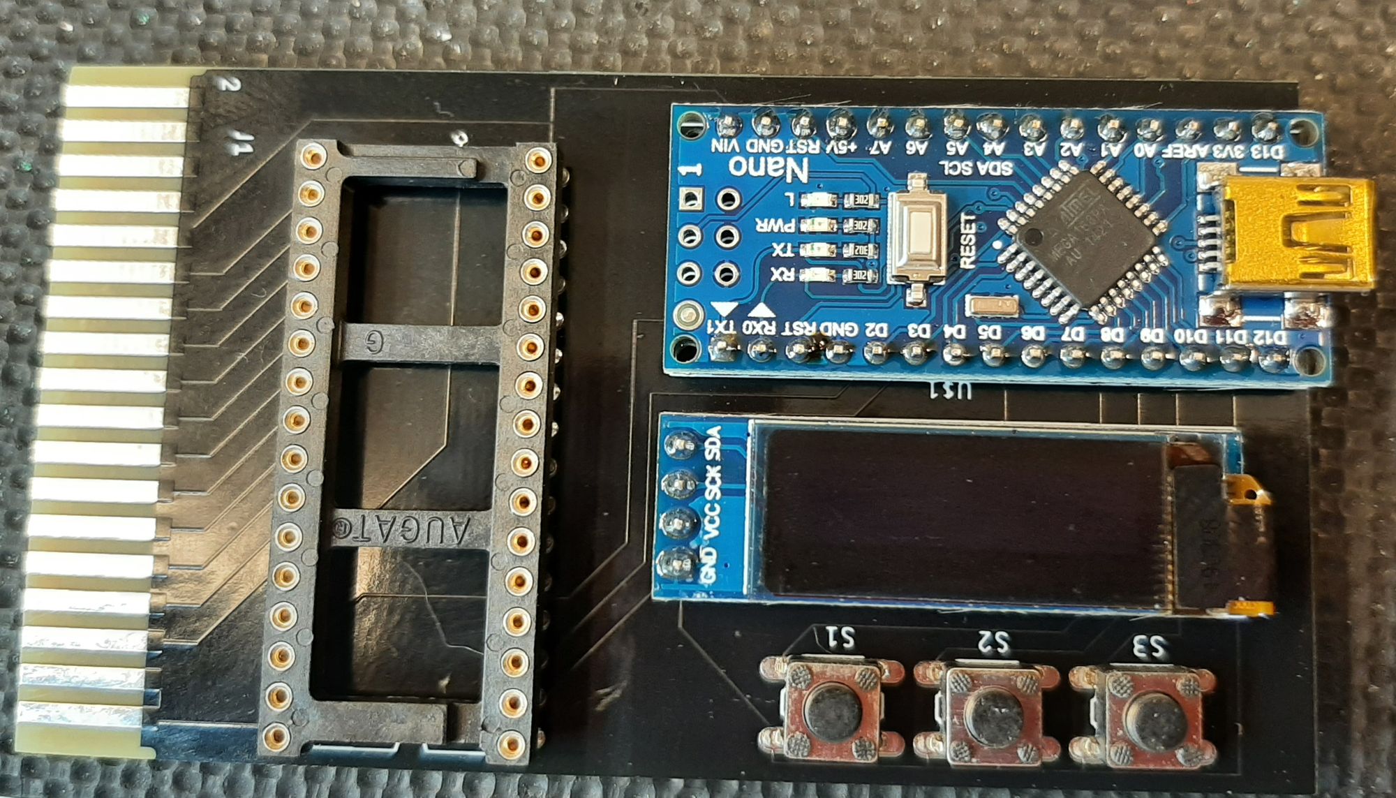
The push buttons will clip into the board , fit and solder these and then fit the 32 pin socket.
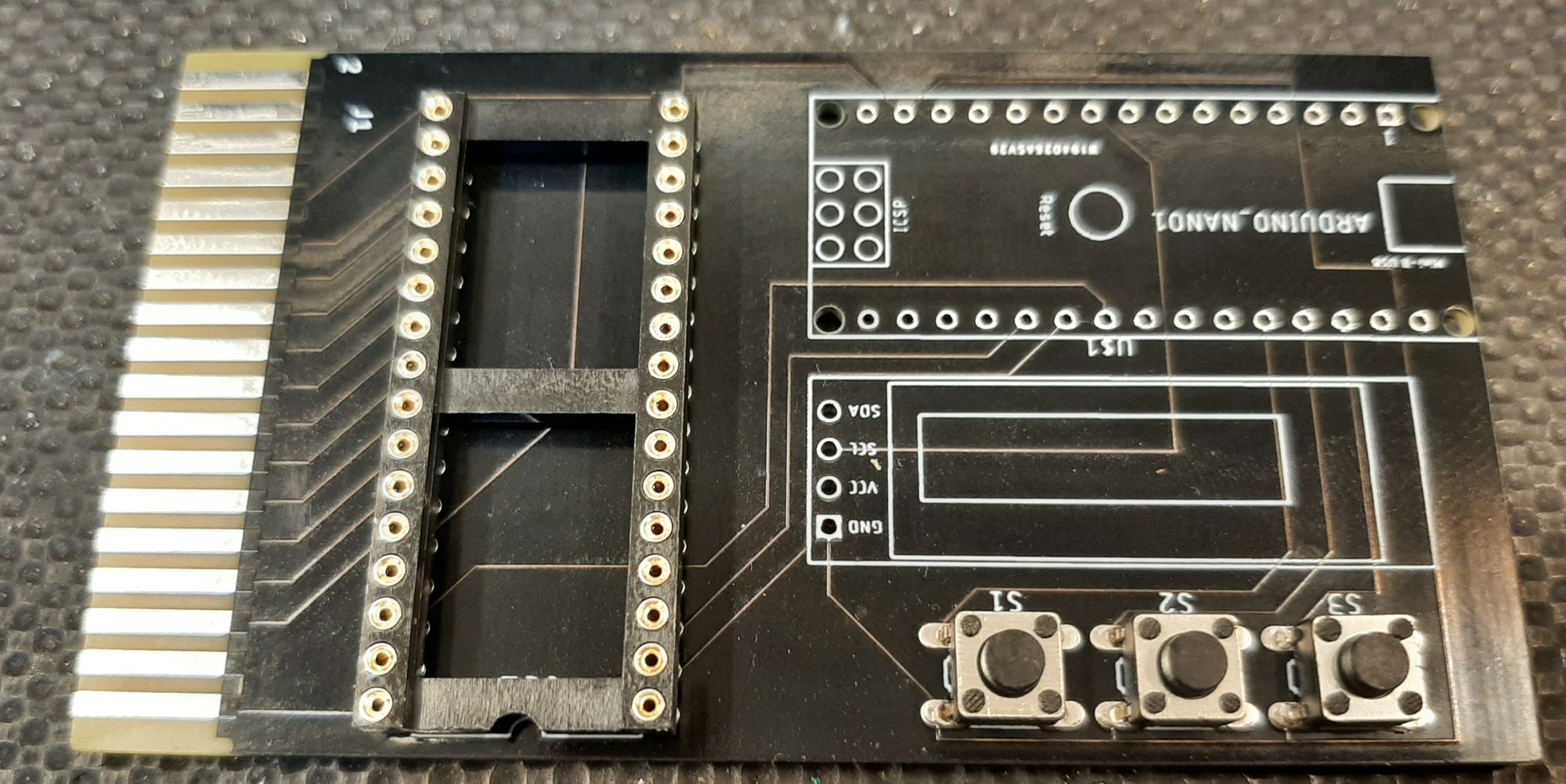
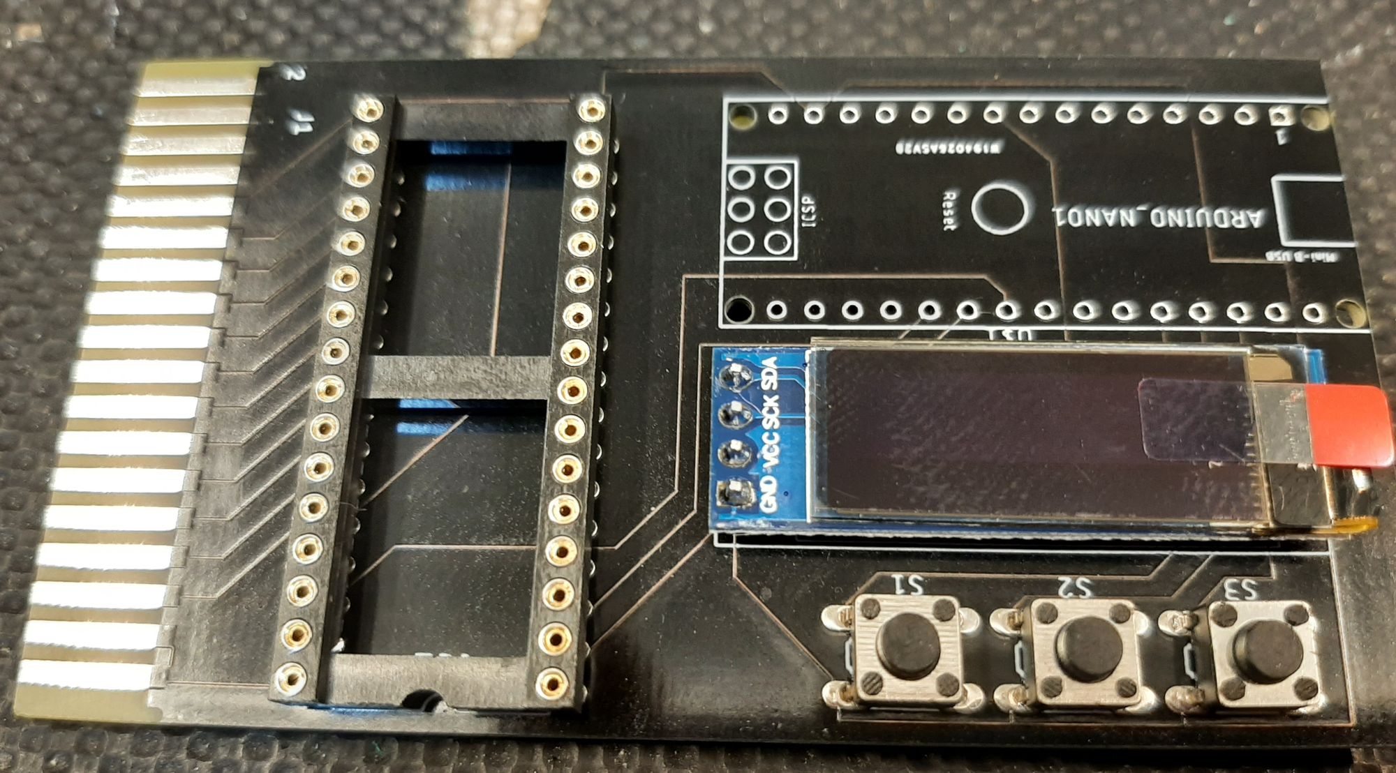
Then fit and solder the oled display , and finally fit the arduino , i found it easier to put the pins in the board and place the arduino on the top BEFORE soldering it and then solder it to the board.
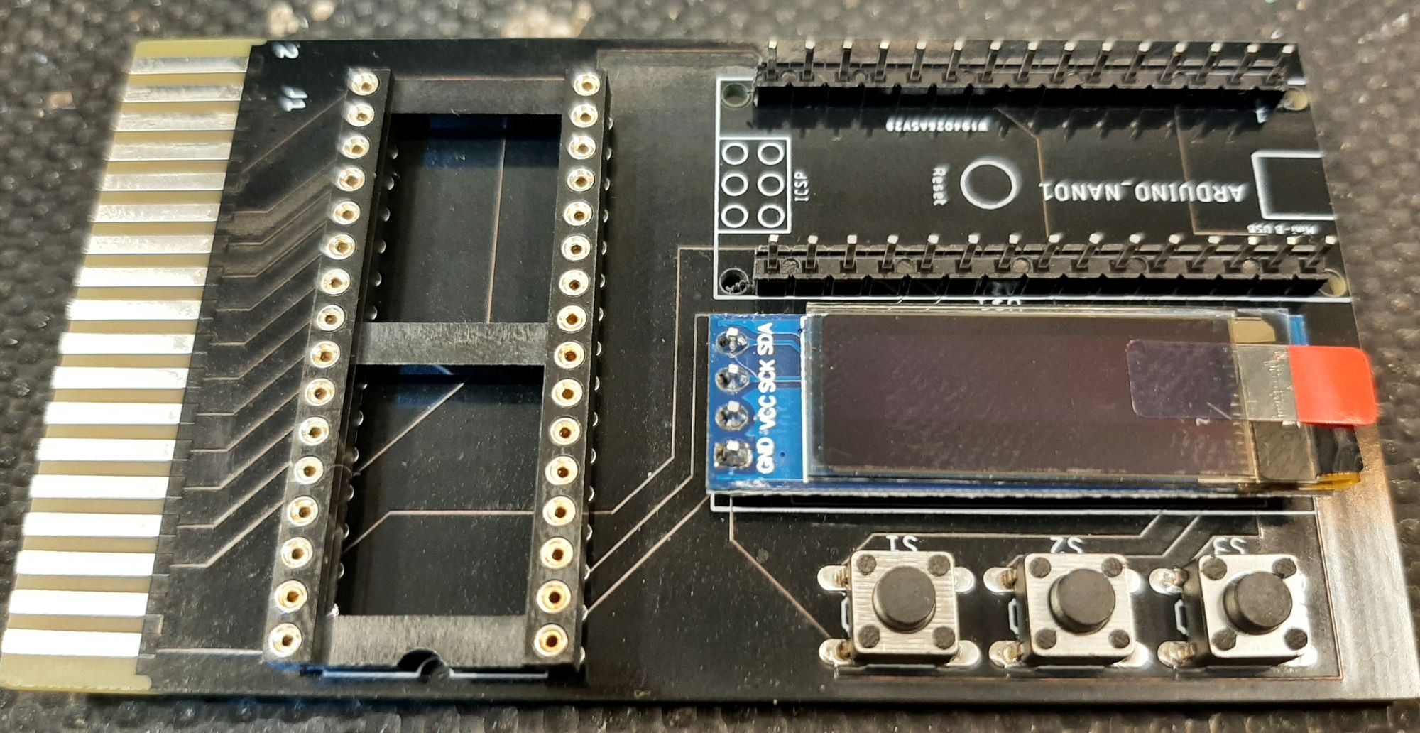
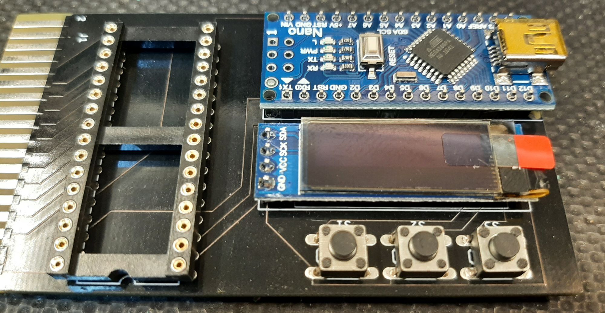
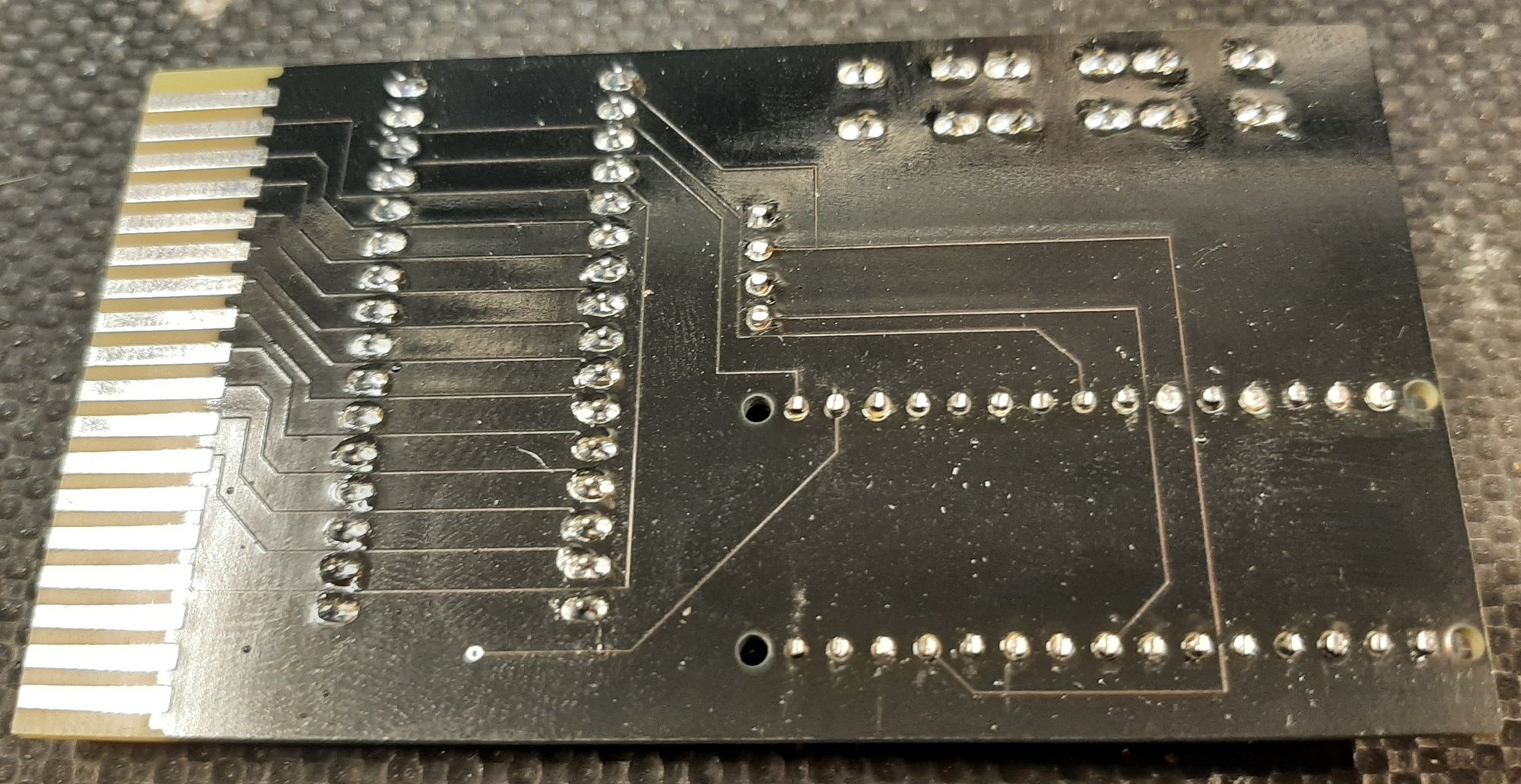
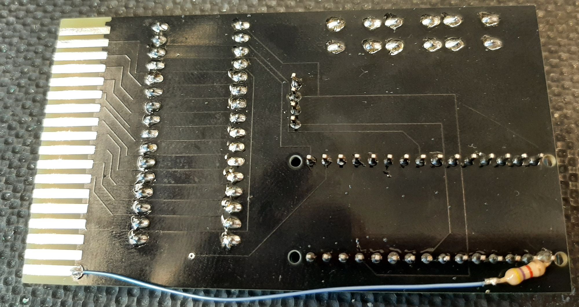
Lastly soder in and clip the legs on the 470R resistor and clip the excess off of the legs on the nano and oled. ( i had to mod the board with some hook-up wire and the resistor )
Remeber there are 2 different boards , one for 8KB rom images and one for 32KB rom images. Both build exactly the same way but the routing on the board is different for each.
Simply click on the image of the board that you require to be taken straight to the PCBWay site to purchase that board.
I do recommend having gold fingers on the edge connector and a 30 degree bevel , you will have to select it on the ordering page!

Next job Programming the Arduino!
I have an Issue 2 pack - so if it works I'll send the details and you will have a…